Hyundai Ioniq (AE): Motor Driven Power Steering / Schematic diagrams
Hyundai Ioniq (AE) 2017-2022 Service & Repair Manual / Steering System / Motor Driven Power Steering / Schematic diagrams
| Schematic Diagrams |
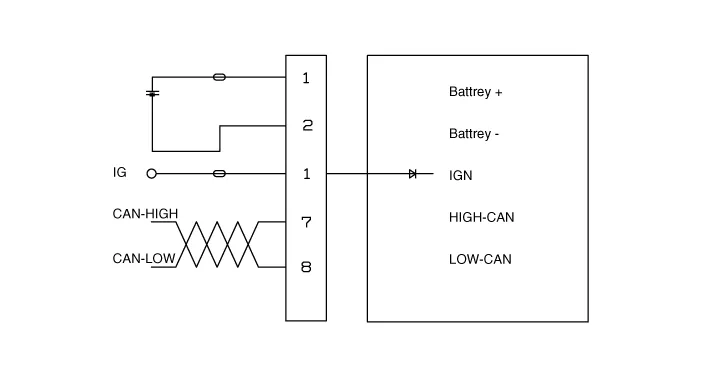
| Terminal Function |
|
Type
|
Pin No
|
Description
|
| Battery | 1 | Battery + |
| 2 | Battery - | |
| VSS | 1 | IGN |
| 2 | - | |
| 3 | - | |
| 4 | - | |
| 5 | - | |
| 6 | - | |
| 7 | HIGH CAN | |
| 8 | LOW CAN |
Components Location1. Steering wheel2. Steering column3. MDPS motor4. MDPS ECU5. Universal joint6. Steering gear box7. Bellows8. Tie rod9. Tie rod end
A/S Repair produresMDPS System A/S Workflow①Noise / malfunction Inspection② Warning lamp (DTC) / CAN Line error2 - 1 Checking Connectors and Wiring1.
Other information:
Hyundai Ioniq (AE) 2017-2022 Service & Repair Manual: Photo Sensor. Repair procedures
Inspection1.Turn the ignition switch ON.2.Connect the GDS.3.Emit intensive light toward the photo sensor using a lamp, and check the output voltage change.4.The voltage will rise with higher intensive light and reduce with lower intensive light.1. Auto light signal2.
Hyundai Ioniq (AE) 2017-2022 Service & Repair Manual: Warning Indicator. Components and components location
C
Categories
- Manuals Home
- Hyundai Ioniq Owners Manual
- Hyundai Ioniq Service Manual
- Transmission Gear Oil. Repair procedures
- Maintenance
- Repair procedures
- New on site
- Most important about car

Copyright © 2026 www.hioniqae.com - 0.0205