
Hyundai Ioniq (AE): Seat Electrical / Seat Heater Switch. Repair procedures
Hyundai Ioniq (AE) 2017-2022 Service & Repair Manual / Body Electrical System / Seat Electrical / Seat Heater Switch. Repair procedures
| Removal |
[Front Seat]
| 1. | Disconnect the negative (-) battery terminal. |
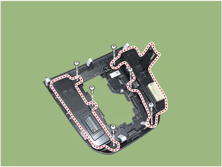
| 2. | Remove the floor console upper cover. (Refer to Body - "Floor Console Assembly") |
| 3. | Remove the seat heater switch after loosening mounting screws.
|
[Rear Seat]
| 1. | Disconnect the negative (-) battery terminal. |
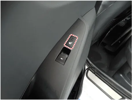
| 2. | Remove the rear door window switch. (Refer to Power Windows - "Power Window Switch") |
| Installation |
[Front Seat Heater Switch]
| 1. | Install the seat heater switch. |
| 2. | Install the floor consol upper cover. |
| 3. | Connect the negative (-) battery terminal. |
[Rear Seat Heater Switch]
| 1. | Install the rear door window switch. |
| 2. | Connect the negative (-) battery terminal. |
Circuit Diagram[Front Seat Heater Switch (Driver)][Front Seat Heater Switch (Passenger)][Rear Seat]
Component Location[Front Ventilation Seat]1. Ventilation seat unit (Assist seat only)2. Ventilation seat blower
Other information:
Hyundai Ioniq (AE) 2017-2022 Service & Repair Manual: Mode Control Actuator. Specifications
S
Hyundai Ioniq (AE) 2017-2022 Service & Repair Manual: Mode Control Actuator. Repair procedures
Inspection1.Turn the ignition switch OFF.2.Disconnect the mode control actuator connector.3.Verify that the mode control actuator operates to the defrost mode when connecting 12V to terminal 3 and grounding terminal 4.Verify that the mode control actuator operates to the vent mode when connected in reverse.
Categories
- Manuals Home
- Hyundai Ioniq Owners Manual
- Hyundai Ioniq Service Manual
- General Information
- Maintenance
- Transmission Gear Oil. Repair procedures
- New on site
- Most important about car

Copyright В© 2026 www.hioniqae.com - 0.0152