
Hyundai Ioniq (AE): Active Air Flap (AAF) / Specifications
| Specifications |
|
Items
|
Specifications
|
| Operating temperature | -31 - 185°F (-35 - 85°C) |
| Operating voltage | DC 9 - 16V |
| Rated voltage | DC 12V |
| Rated current (No load) | 300mA or less |
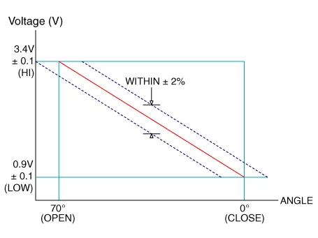
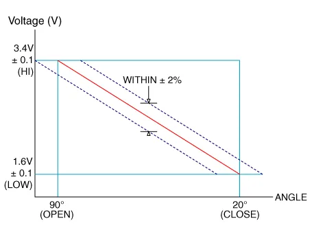
DescriptionThe AAF (Active Air Flap) is located between radiator grille and radiator, and consists of an actuator and 6 air flaps. The system receives information from EMS, FATC, TCU, MCU and LDC via CAN communication .
Components1. Air duct2. Flap3. Housing4. Actuator assembly
Other information:
Hyundai Ioniq (AE) 2017-2022 Service & Repair Manual: Photo Sensor. Description and operation
Description The photo sensor is located at the center of the defrost nozzles.The photo sensor contains a photovoltaic (sensitive to sunlight) diode. The solar radiation received by its light receiving portion, generates an electromotive force in proportion to the amount of radiation received which is transferred to the automatic temperature control
Hyundai Ioniq (AE) 2017-2022 Service & Repair Manual: Blower Motor. Repair procedures
Inspection1.Connect the battery voltage and check the blower motor rotation.2.If the blower motor does not operate well, substitute with a known-good blower motor and check for proper operation.3.Replace the blower motor if it is proved that there is a problem with it.
Categories
- Manuals Home
- Hyundai Ioniq Owners Manual
- Hyundai Ioniq Service Manual
- Hybrid Vehicle Engine Compartment
- DCT(Dual Clutch Transmission) System
- Components and components location
- New on site
- Most important about car
