Hyundai Ioniq (AE): AVN System / AVN Remote Controller. Schematic diagrams
| Circuit Diagram |
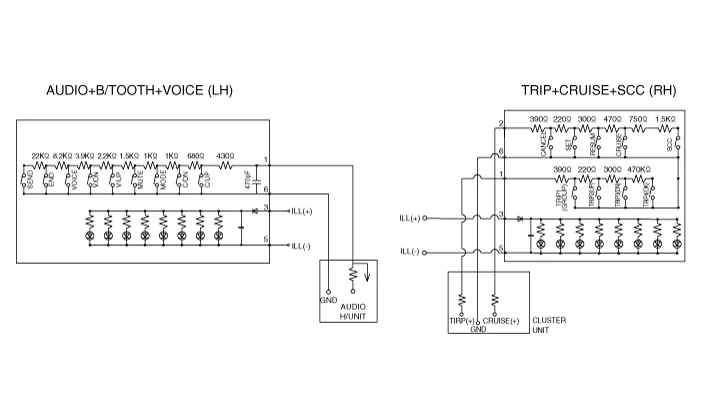

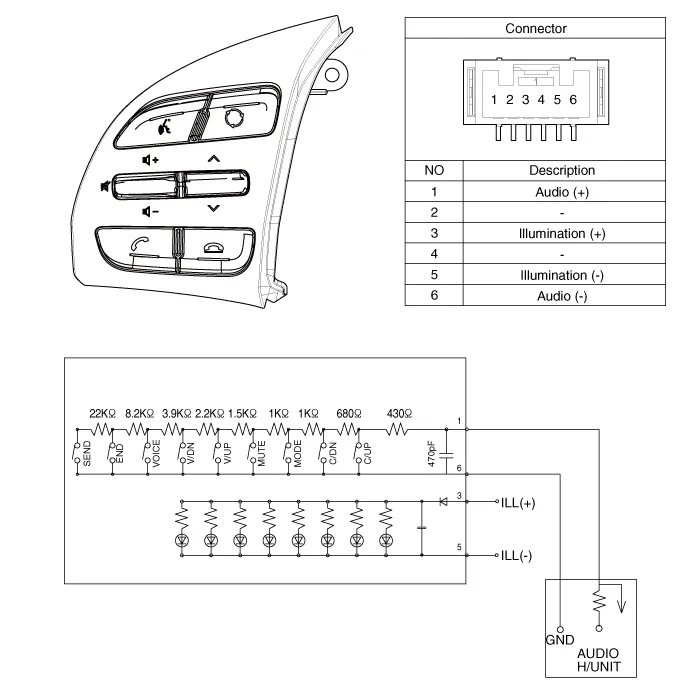
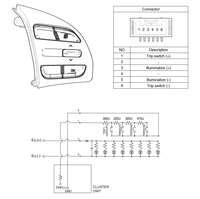
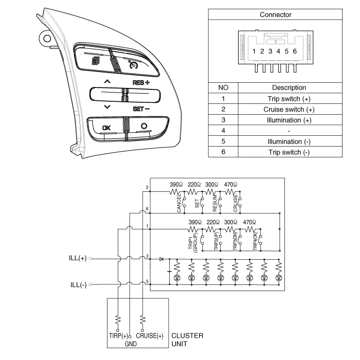

Components1. Left Remote Control Switch (Audio + Hands free)2. Right Remote Control Switch(Cruise+Trip Computer)
Inspection1.Check for resistance between terminals in each switch position (LH).[LH : Audio+B/TOOTH+VOICE] Switch Connector terminal Resistance (±5%) SEEK Up1-6430 ΩSEEK Down1.
Other information:
Hyundai Ioniq (AE) 2017-2022 Service & Repair Manual: Mode Control Actuator. Description and operation
DescriptionThe mode control actuator is located at the heater unit.It adjusts the position of the mode door by operating the mode control actuator based on the signal of the A/C control unit. Pressing the mode select switch makes the mode control actuator shift in order of Vent → Bi-Level → Floor → Mix.
Hyundai Ioniq (AE) 2017-2022 Service & Repair Manual: Description and operation
Cruise ControlThe cruise control system is engaged by the cruise "ON/OFF" main switch located on right of steering wheel column. The system has the capability to cruise, coast, accelerate and resume speed.It also has a safety interrupt, engaged upon depressing brake or shifting select lever.
Categories
- Manuals Home
- Hyundai Ioniq Owners Manual
- Hyundai Ioniq Service Manual
- Hybrid Vehicle Engine Compartment
- Brake System
- Jump Starting
- New on site
- Most important about car
