Hyundai Ioniq (AE): Driveshaft Assembly / BJ Boot. Repair procedures
Hyundai Ioniq (AE) 2017-2022 Service & Repair Manual / Driveshaft and axle / Driveshaft Assembly / BJ Boot. Repair procedures
| Replacement |
| 1. | Remove the front driveshaft. (Refer to Driveshaft Assembly - "Front Driveshaft") |
| 2. | Remove the TJ joint assembly. (Refer to Driveshaft Assembly - "TJ Joint") |
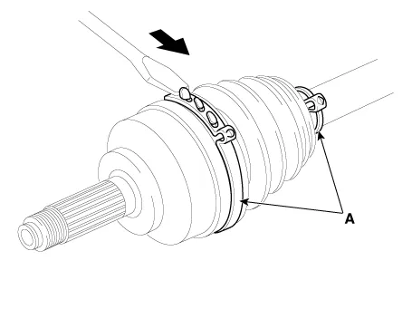
| 3. | Using a plier or flat-tipped (-) screwdriver, remove the BJ boot bands (A).
|
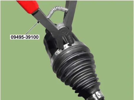
| 4. | Using the SST, secure the BJ boot bands. [Hook type]
[Ear type]
|


| 5. | Install the TJ joint assembly. (Refer to Driveshaft Assembly - "TJ joint") |
| 6. | Install the front driveshaft. (Refer to Driveshaft Assembly - "Front Driveshaft") |
| 7. | Check the front alignment. (Refer to Suspension System - "Front Alignment") |
Components1. BJ assembly 2. Circlip 3. BJ boot band 4. BJ boot 5. Shaft6. TJ boot band7. TJ boot8. Spider assembly9. Snap ring10. TJ Case11. Clip
Other information:
Hyundai Ioniq (AE) 2017-2022 Service & Repair Manual: Mode Control Actuator. Description and operation
DescriptionThe mode control actuator is located at the heater unit.It adjusts the position of the mode door by operating the mode control actuator based on the signal of the A/C control unit. Pressing the mode select switch makes the mode control actuator shift in order of Vent → Bi-Level → Floor → Mix.
Hyundai Ioniq (AE) 2017-2022 Service & Repair Manual: Components and components location
C
Categories
- Manuals Home
- Hyundai Ioniq Owners Manual
- Hyundai Ioniq Service Manual
- Suspension System
- Engine Control/Fuel System
- Engine Mechanical System
- New on site
- Most important about car

Copyright © 2026 www.hioniqae.com - 0.0225