Hyundai Ioniq (AE): Brake System / Brake Pedal. Repair procedures
| Removal |
| 1. | Turn ignition switch OFF and disconnect the negative (-) battery cable. |
| 2. | Remove the crash pad lower panel. (Refer to Body - "Crash Pad") |
| 3. | Remove the knee air bag. (Refer to Restraint - "Knee Airbag (KAB) Module") |
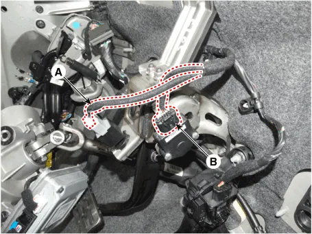
| 4. | Disconnect the stop lamp switch connector (A) and the brake pedal stroke sensor connector (B).
|
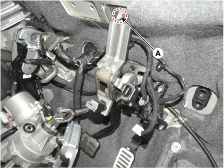
| 5. | Remove the brake pedal member mounting nut (A).
|
| 6. | Remove the snap pin (A) and clevis pin (B).
|

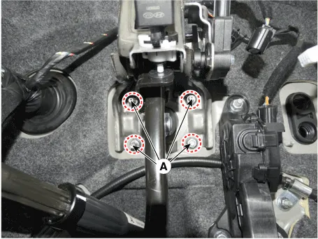
| 7. | Remove the mounting nuts (A) and then remove the brake pedal.
|
| Installation |
| 1. | Install in the reverse of removal. |
| 2. | Check the brake pedal operation. |
| 3. | Conduct calibration after removing the brake pedal assembly. |
| Adjustment |
| • | After changing the brake pedal assembly (you cannot change only the sensor). |
| • | After changing the IBAU (Intergrated Brake Actuation Unit). |
| • | When error codes C1380 (calibration) or C1379 (signal error) are detected. |
| • | After bleeding IBAU & PSU line. |
| 1. | Connect the GDS. (CAN line or OBD connector) |
| 2. | Turn ignition switch ON. |
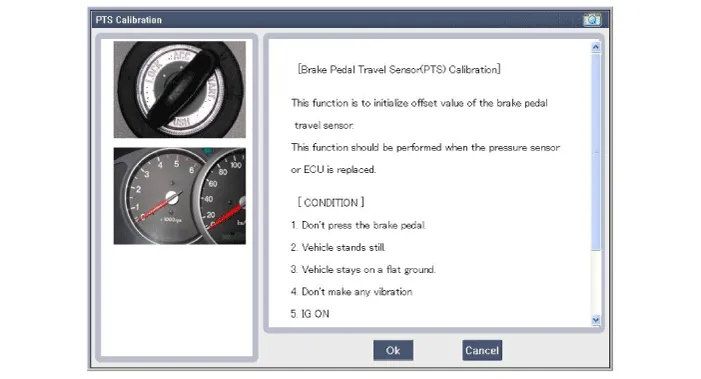
| 3. | Select calibration of the brake pedal sensor. |
| 4. | Follow prompts displayed on the GDS screen to complete brake pedal sensor calibration.
|
| 5. | Turn ignition switch off after calibration procedure. |
| 6. | Confirm success or failure of calibration. |
Components 1. Brake pedal member assembly2. Stop lamp switch3. Brake pedal arm4. Brake pedal pad5. Brake pedal stroke sensor
Components1. Bleed screw2. Caliper body3. Pad inner shim4. Brake pad5. Pad return spring6. Caliper carrier7. Pad retainer
Other information:
Hyundai Ioniq (AE) 2017-2022 Service & Repair Manual: A/C Pressure Transducer. Repair procedures
Inspection • Before measuring the pressure of the refriferant line, check whether the refrigerant amount is charged in accordance with the specified charging amount.(Refer to Heating, Ventilation, Air Conditioning - "Specifications")1.
Hyundai Ioniq (AE) 2017-2022 Service & Repair Manual: Auto Defogging Sensor. Description and operation
DescriptionThe auto defogging sensor is installed on the front window glass. The sensor judges and sends signal if moisture occurs to blow out wind for defogging. The air conditioner control module receives signal from the sensor and restrains moisture and eliminate defog by controlling the intake actuator, A/C, auto defogging actuator, blower moto
Categories
- Manuals Home
- Hyundai Ioniq Owners Manual
- Hyundai Ioniq Service Manual
- Jump Starting
- How to Connect Portable Charger (ICCB: In-Cable Control Box)
- Engine Clutch System
- New on site
- Most important about car
