Hyundai Ioniq (AE): Cylinder Block / Cylinder Block. Repair procedures
Hyundai Ioniq (AE) 2017-2022 Service & Repair Manual / Engine Mechanical System / Cylinder Block / Cylinder Block. Repair procedures
| Disassembly |
|

|

|

| 1. | Remove the engine assembly from the vehicle. (Refer to Engine and Transaxle Assembly - "Engine and Transaxle Assembly") |
| 2. | Remove the transaxle assembly from the engine assembly. (Refer to Double Clutch Transmission (DCT) System - "Double Clutch Transmission (DCT)") |
| 3. | Remove the flywheel. (Refer to Cylinder Block - "Flywheel") |
| 4. | Remove the rear oil seal. (Refer to Cylinder Block - "Rear Oil Seal") |
| 5. | Install the engine to engine stand for disassembly. |
| 6. | Remove the intake manifold. (Refer to Intake and Exhaust System - "Intake Manifold") |
| 7. | Remove the exhaust manifold. (Refer to Intake and Exhaust System - "Exhayst Manifold") |
| 8. | Remove the hybrid starter generator (HSG). (Refer to Hybrid Motor System - "Hybrid Starter Generator (HSG)") |
| 9. | Remove the timing chain. (Refer to Timing System - "Timing Chain") |
| 10. | Remove the cylinder head assembly. (Refer to Cylinder Head Assembly - "Cylinder Head") |
| 11. | Remove the thermostat. (Refer to Cooling System - "Thermostat") |
| 12. | Remove the EGR cooler. (Refer to Intake and Exhaust System - "EGR Cooler") |
| 13. | Remove the A/C compressor. (Refer to Heating, Ventilation Air conditioning -"Compressor") |
| 14. | Remove the knock sensor. (Refer to Engine Control / Fuel System - "Knock Sensor") |
| 15. | Remove the oil pan and oil screen. (Refer to Lubrication System - "Oil Pan") |
| 16. | Remove the ladder frame. (Refer to Cylinder Block - "Piston and Connecting Rod") |
| 17. | Remove the piston and connecting rod assemblies. (Refer to Cylinder Block - "Piston and Connecting Rod") |
| 18. | Remove the crankshaft. (Refer to Cylinder Block - "Crankshaft") |
| 19. | Remove the crankshaft position sensor (CKPS). (Refer to Engine Control / Fuel System - "Crankshaft Position Sensor (CKPS)") |
| 20. | Remove the oil pressure switch. (Refer to Lubrication System - "Oil Pressure Switch") |
| 21. | Remove the water jacket separator. (Refer to Cylinder Block - "Water Jacket Separator") |
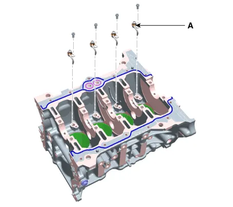
| 22. | Remove the piston cooling jet (A).
|
| Inspection |
Cylinder Block
| 1. | Remove the gasket material. Using a gasket scraper, remove all the gasket material from the top surface of the cylinder block. |
| 2. | Clean the cylinder block. Using a soft brush and solvent, thoroughly clean the cylinder block. |
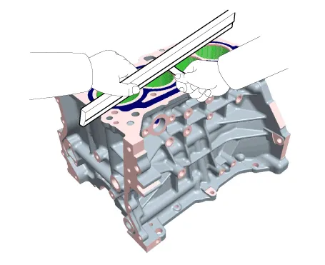
| 3. | Inspect the top surface of the cylinder block for flatness. Using a precision straight edge and feeler gauge, measure the surface contacting the cylinder head gasket for warpage.
|
| 4. | Inspect the cylinder bore. Visually check the cylinder for vertical scratchs. If deep scratchs are present, replace the cylinder block. |
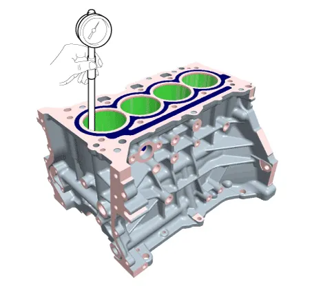
| 5. | Inspect the cylinder bore diameter. Using a cylinder bore gauge, measure the cylinder bore diameter at position in the thrust and axial direction.
|
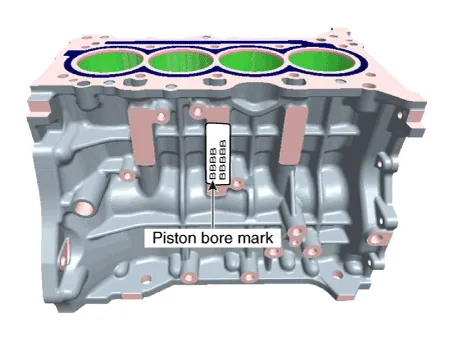
| 6. | Check the cylinder bore size code on the cylinder block.
Discrimination of cylinder bore size
|
| Reassembly |
|
| 1. | Install the piston cooling jet (A).
|
| 2. | Assemble the other parts in the reverse order of disassembly.
|

Disassembly • Be sure to read and follow the "General Safety Information and Caution" before doing any work related with the high voltage system.
Other information:
Hyundai Ioniq (AE) 2017-2022 Service & Repair Manual: General safety information and caution
General Safety Information and CautionBe careful of the following precautions when driving the vehicle using the smart cruise control system. • The smart cruise control system may have limits in detecting distance to the vehicle ahead due to road and traffic conditions.
Hyundai Ioniq (AE) 2017-2022 Service & Repair Manual: Schematic diagrams
System Block DiagramComponent Parts and Function Outline Component part Function Vehicle-speed sensor, ESP/ABS Control ModuleConverts vehicle speed to pulse.VCUReceives signals from sensor and control switches.
Categories
- Manuals Home
- Hyundai Ioniq Owners Manual
- Hyundai Ioniq Service Manual
- Checking the Coolant Level
- Jump Starting
- Body (Interior and Exterior)
- New on site
- Most important about car

Copyright © 2026 www.hioniqae.com - 0.0197