Hyundai Ioniq (AE): Cylinder Block / Crankshaft. Repair procedures
Hyundai Ioniq (AE) 2017-2022 Service & Repair Manual / Engine Mechanical System / Cylinder Block / Crankshaft. Repair procedures
| Disassembly |
|

|

|

| 1. | Remove the engine assembly from the vehicle. (Refer to Engine and Transaxle Assembly - "Engine and Transaxle Assembly") |
| 2. | Remove the transaxle assembly from the engine assembly. (Refer to Double Clutch Transmission (DCT) System - "Double Clutch Transmission (DCT)") |
| 3. | Remove the flywheel. (Refer to Cylinder Block - "Flywheel") |
| 4. | Remove the rear oil seal. (Refer to Cylinder Block - "Rear Oil Seal") |
| 5. | Install the engine to engine stand for disassembly. |
| 6. | Remove the intake manifold. (Refer to Intake and Exhaust System - "Intake Manifold") |
| 7. | Remove the exhaust manifold. (Refer to Intake and Exhaust System - "Exhayst Manifold") |
| 8. | Remove the hybrid starter generator (HSG). (Refer to Hybrid Motor System - "Hybrid Starter Generator (HSG)") |
| 9. | Remove the timing chain. (Refer to Timing System - "Timing Chain") |
| 10. | Remove the cylinder head assembly. (Refer to Cylinder Head Assembly - "Cylinder Head") |
| 11. | Remove the thermostat. (Refer to Cooling System - "Thermostat") |
| 12. | Remove the EGR cooler. (Refer to Intake and Exhaust System - "EGR Cooler") |
| 13. | Remove the A/C compressor. (Refer to Heating, Ventilation Air conditioning -"Compressor") |
| 14. | Remove the knock sensor. (Refer to Engine Control / Fuel System - "Knock Sensor") |
| 15. | Remove the oil pan and oil screen. (Refer to Lubrication System - "Oil Pan") |
| 16. | Remove the ladder frame. (Refer to Cylinder Block - "Piston and Connecting Rod") |
| 17. | Remove the piston and connecting rod assemblies. (Refer to Cylinder Block - "Piston and Connecting Rod") |
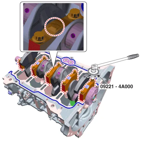
| 18. | Remove the main bearing caps and check oil clearance. |
| 19. | Check the crankshaft end play. |
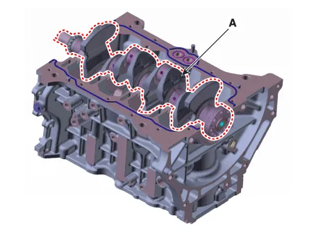
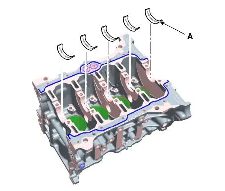
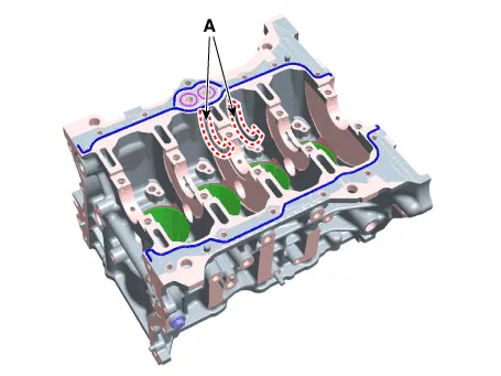
| 20. | Lift the crankshaft (A) out of engine, being careful not to damage journals.
|
| Inspection |
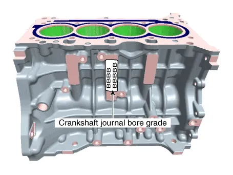
| 1. | Check the crankshaft bearing oil clearance.
| |||||||||||||||||||||||||||||||||||||||||||||||||||||||||||||||||||||||||||||||||||||||||||||||||||
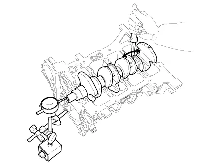
| 2. | Check crankshaft end play. Using a dial indicator, measure the thrust clearance while prying the crankshaft back and forth with a screwdriver.
If the end play is greater than maximum, replace the center bearings as a set. |
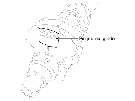
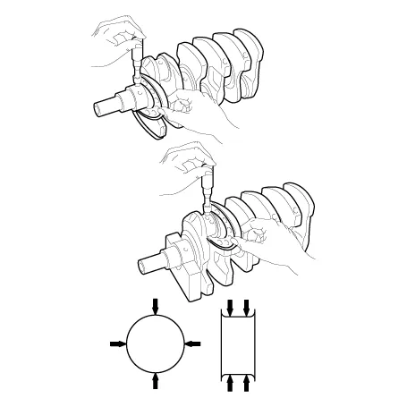
| 3. | Inspect the crankshaft main journals and pin journals. Using a micrometer, measure the diameter of each main journal and pin journal.
|
| Reassembly |
|
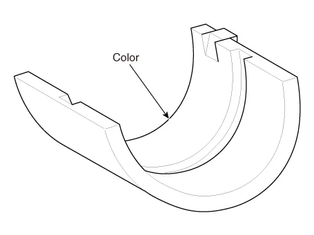
| 1. | Install the crankshaft main bearings.
|
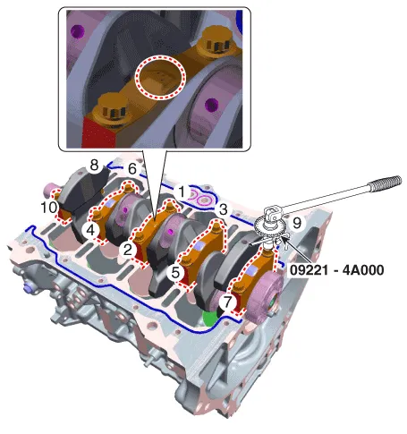
| 2. | Place the crankshaft (A) on the cylinder block.
|
| 3. | Install the main bearing cap (A).
|
| 4. | Check the crankshaft end play. |
| 5. | Assemble the other parts in the reverse order of disassembly. |
Components1. Thrust bearing2. Main bearing (Upper)3. Crankshaft4. Main bearing (Lower)5. Main bearing cap
Disassembly • Be sure to read and follow the "General Safety Information and Caution" before doing any work related with the high voltage system.
Other information:
Hyundai Ioniq (AE) 2017-2022 Service & Repair Manual: emperature Control Actuator. Specifications
S
Hyundai Ioniq (AE) 2017-2022 Service & Repair Manual: Description and operation
DescriptionBlcok DiagramFunctions of Front View CameraFront View Camera supports the following functions using the information (lane, light source, vehicle and pedestrian) detected by the front view camera and the vehicle's signal information (CAN communication).
Categories
- Manuals Home
- Hyundai Ioniq Owners Manual
- Hyundai Ioniq Service Manual
- DCT(Dual Clutch Transmission) System
- Repair procedures
- Brake System
- New on site
- Most important about car

Copyright © 2026 www.hioniqae.com - 0.0168