Hyundai Ioniq (AE): Lighting System / Hazard Lamp Switch. Repair procedures
| Inspection |
| 1. | The SJB can be diagnosed by using the GDS. The SJB communicates with the GDS which then displays inputs and outputs along with codes. It will be able to diagnose defects of hazard lamp switch with GDS quickly. GDS can operates actuator forcefully, input/output value monitoring and self diagnosis. |
| 2. | To diagnose the SJB function, select the vehicle model, BCM and SJB. |
| 3. | To consult the present input/out value of SJB, "Current DATA". It provides information of SJB input/output conditions. |
| Removal |
|

| 1. | Disconnect the negative (-) battery terminal. |
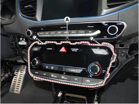
| 2. | Remove the crash pad side garnish [RH] (A). (Refer to Body - "Glove Box Upper Cover Assembly") |
| 3. | After loosening the mounting screws, remove the A/C & heater controller unit (A).
|
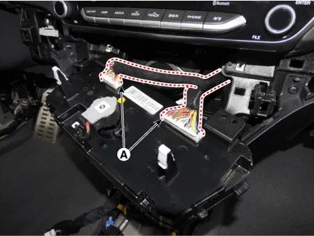
| 4. | Disconnect the A/C & heater controller unit (A)..
|
| 5. | To intall, reverse the removal procedure. |
|

| Installation |
| 1. | Install the center facia panel switch assembly. |
| 2. | Connect the negative (-) battery terminal. |
Inspection1.Remove the overhead console lamp assembly then check for continuity between terminals. If the continuity is not as specified, replace the map lamp switch.
Other information:
Hyundai Ioniq (AE) 2017-2022 Service & Repair Manual: In-car Sensor. Repair procedures
Diagnosis With GDS1.The heating, ventilation and air conditioning can be quickly diagnosed failed parts with vehicle diagnostic system (GDS).※ The diagnostic system (GDS) provides the following information.(1) Self diagnosis : Checking the failure code (DTC) and display.
Hyundai Ioniq (AE) 2017-2022 Service & Repair Manual: Warning Indicator. Repair procedures
RemovalWarning Indicator1.Disconnect the negative (-) battery terminal.2.Remove the mirror (A).InstallationWarning Indicator1.Install the outside mirror.2.Connect the negative (-) battery terminal.Inspection1.Apply battery voltage to each terminal as shown in the table and verify that the mirror operates properly.
Categories
- Manuals Home
- Hyundai Ioniq Owners Manual
- Hyundai Ioniq Service Manual
- Jump starting procedure
- Transmission Gear Oil. Repair procedures
- Heating, Ventilation and Air Conditioning
- New on site
- Most important about car
