Hyundai Ioniq (AE): Hybrid Motor Assembly / Hybrid Drive Motor Assembly. Repair procedures
| Inspection |
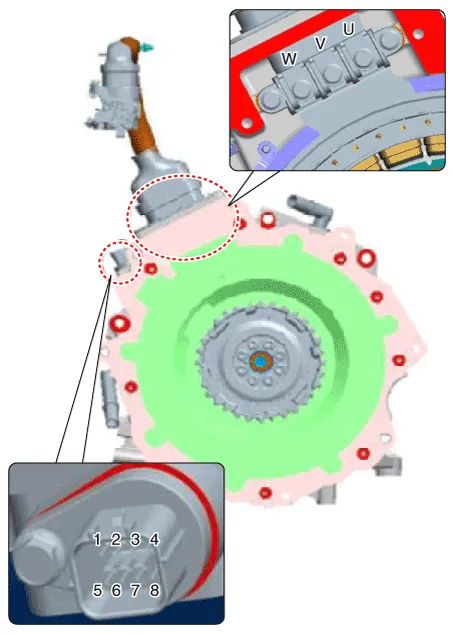
| 1. | Use the mΩ tester to check the line resistance.
|
| 2. | Check the temperature sensor resistance.
|
| 3. | Check the resolver sensor resistance.
|
| 4. | Perform the insulation test.
|
| Removal |
| 1. | Remove the double clutch transmission (DCT) from the vehicle. (Refer to DCT (Double Clutch Transmission) System - "Double Clutch Transmission".) |
| 2. | Remove the water pump (EWP) (A).
|
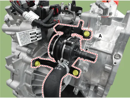
| 3. | Disconnect the reservoir hose (A).
|

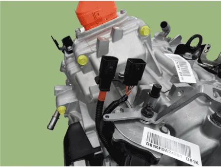
| 4. | Remove the engine clutch actuator (B).
|
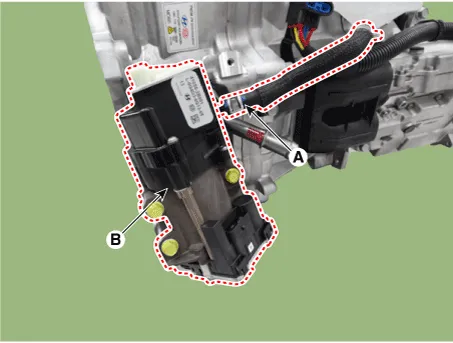
| 5. | Remove the adaptor (A).
|
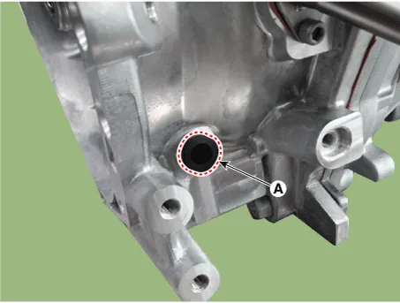
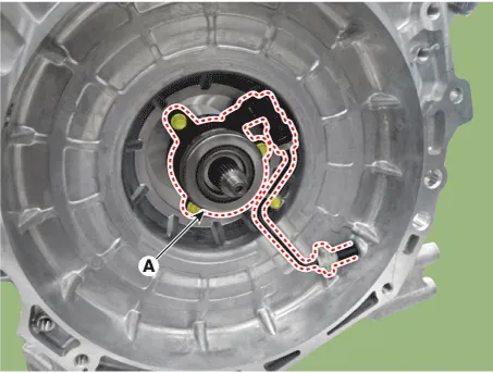
| 6. | Remove the concentric sleeve cylinder (A).
|
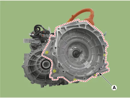
| 7. | Unscrew the bolts and remove the motor assembly (A).
|
| Installation |
| 1. | To install, reverse the removal procedure.
|

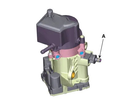
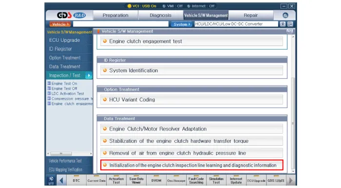
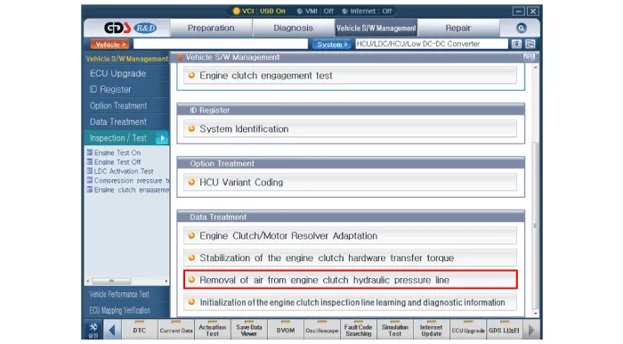
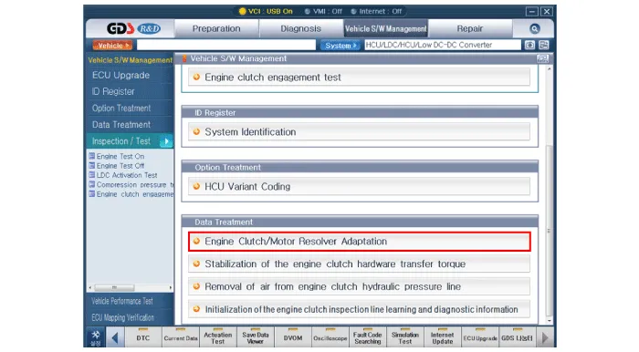
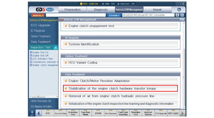
| 2. | After replacing the Engine clutch actuator, operate the followings in order using GDS equipment.
|

Component location1. HPCU (Hybrid Power Control Unit)(LDC+MCU+HCU+Reservoir)2. Hybrid drive motor3. Hybrid starter generator (HSG)4. Electrical radiator5.
Component location1. HPCU (Hybrid Power Control Unit)(LDC+MCU+HCU+Reservoir)2. Hybrid drive motor3. Hybrid starter generator (HSG)4. Electrical radiator5.
Other information:
Hyundai Ioniq (AE) 2017-2022 Service & Repair Manual: Description and operation
DescriptionIn ordinary cars, the mechanical water pump mounted on the engine for heating purposes is activated to circulate the cooling water, but in hybrid cars, AEWP is used to circulate the cooling water when the engine is not operating. Classification System Cooling water used
Hyundai Ioniq (AE) 2017-2022 Service & Repair Manual: Parking Distance Warning (PDW) ON/OFF Switch. Repair procedures
Removal • Put on gloves to prevent hand injuries. • When removing with a flat-tip screwdriver or remover, wrap protective tape around the tools to prevent damage to components.
Categories
- Manuals Home
- Hyundai Ioniq Owners Manual
- Hyundai Ioniq Service Manual
- Front Disc Brake. Repair procedures
- Repair procedures
- Engine Control/Fuel System
- New on site
- Most important about car
