Hyundai Ioniq (AE): AHB(Active Hydraulic Boost) System / Hydraulic Power Unit. Repair procedures
| Removal |
| 1. | Turn ignition switch OFF and disconnect the negative (-) battery cable. |
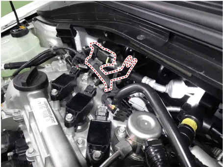
| 2. | Remove the wiring bracket.
|
| 3. | Remove the brake fluid from the reservoir with a syringe.
|

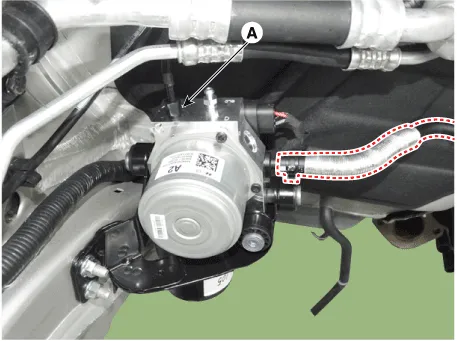
| 4. | Loosening the flare nut (A) and then disconnect the brake tube.
|

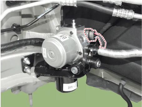
| 5. | Disconnect the PSU connector.
|
| 6. | Remove the front sub frame. (Refer to Suspension System - "Sub Frame") |
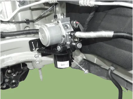
| 7. | Loosen the mounting bolt and nut then remove the PSU.
|
| Installation |
| 1. | Installation is the reverse of removal. |
| 2. | Tighten the PSU bracket bolts and brake tube to the specified torque. |
| 3. | After filling the brake fluid in the reservoir, perform the air bleed. . (Refer to AHB System - "AHB System Air Bleeding") |
| 4. | Conduct Pressure sensor Calibration. |
| 5. | Check the brake pedal operation. |
| Diagnostic Procedure Using GDS |
| 1. | Connect the diagnostic instrument to the self-diagnostic connector (16-pin) beneath the crash pad on the side of driver's seat, and then turn on the ignition to activate the diagnostic instrument. |
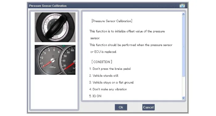
| 2. | In the GDS Vehicle Type Selection menu, select "Vehicle Type" and "ABS/ESC" System, and then opt for "OK." [Pressure Sensor Calibration]
|
| 3. | Turn ignition switch off and on after calibration procedure. |
| 4. | Confirm success of calibration. |
Components • PSU (Presser Source Unit) must not be disassembled.1. Pressure Source Unit (PSU)2. Pressure Source Unit (PSU) connector3.
Other information:
Hyundai Ioniq (AE) 2017-2022 Service & Repair Manual: Heater Unit. Repair procedures
Replacement When prying with a flat-tip screwdriver or use a prying trim tool, wrap it with protective tape, and apply protective tape around the related parts, to prevent damage.1.Disconnect the negative (-) battery terminal.2.Recover the refrigerant with a recovery / recycling / charging station.
Hyundai Ioniq (AE) 2017-2022 Service & Repair Manual: Front Radar Unit. Repair procedures
Removal1.Remove the front bumper.(Refer to Body - "Front Bumper")2.Disconnect the smart cruise control unit connector (A).3.Remove the smart cruise control nuit assembly (B) from thevehicle after loosening mounting bolts.Installation1.Install in the reverse order of removal.
Categories
- Manuals Home
- Hyundai Ioniq Owners Manual
- Hyundai Ioniq Service Manual
- Hybrid Vehicle Engine Compartment
- DCT(Dual Clutch Transmission) System
- Engine Mechanical System
- New on site
- Most important about car
