Hyundai Ioniq (AE): High Voltage Battery Control System / Main Fuse. Repair procedures
Hyundai Ioniq (AE) 2017-2022 Service & Repair Manual / Hybrid Control System / High Voltage Battery Control System / Main Fuse. Repair procedures
| Removal |
|

| 1. | Shut off the high voltage. (Refer to Hybrid Control System - "High Voltage Shut-off Procedures") |
| 2. | Remove the rear seat cushion. (Refer to Body - "Rear Seat Assembly") |
| 3. | Remove the rear door scuff trim. (Refer to Body - "Door Scuff Trim") |
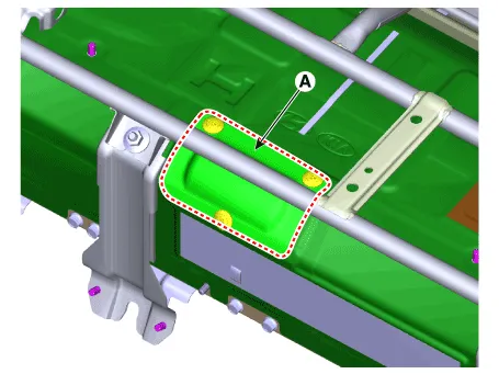
| 4. | Remove the cover (A).
|
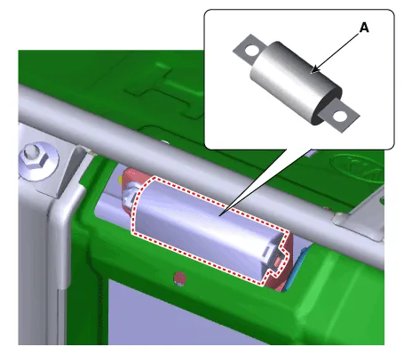
| 5. | Remove the main fuse cover and then revmoing the main fuse (A).
|
| Installation |
|
| 1. | Install the main fuse in the reverse order of removal.
|

| Inspection |
| 1. | Remove the main fuse. (Refer to High Voltage Battery Control System - "Main Fuse") |
| 2. | Check the continuity between ends of the main fuse.
|
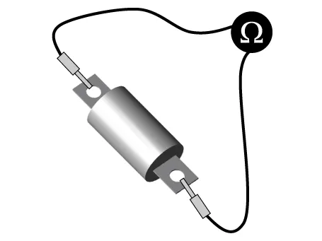
| 3. | If the measured resistance is not within the spec value, then exchange the main fuse by following the maintenance guideline. |
Circuit Diagram
DescriptionBattery Temperature Sensor is installed inside the high voltage battery pack assembly. It measures the temperature of the battery module 1, 4 and air inlet.
Other information:
Hyundai Ioniq (AE) 2017-2022 Service & Repair Manual: Mode Control Actuator. Components and components location
C
Hyundai Ioniq (AE) 2017-2022 Service & Repair Manual: Description and operation
DescriptionRear view monitor (RVM) will activate when the backup light is ON with the ignition switch ON and the shift lever in the R position.This system is a supplemental system that shows behind the vehicle through the AV monitor while backing-up. • This system is a supplementary function only.
Categories
- Manuals Home
- Hyundai Ioniq Owners Manual
- Hyundai Ioniq Service Manual
- Jump starting procedure
- Heating, Ventilation and Air Conditioning
- Engine Control/Fuel System
- New on site
- Most important about car

Copyright © 2026 www.hioniqae.com - 0.0235