Hyundai Ioniq (AE): High Voltage Battery Control System / Pre Charge Relay. Repair procedures
| Removal |
| 1. | Shut off the high voltage. (Refer to Hybrid Control System - "High Voltage Shut-off Procedures") |
| 2. | Remove the rear seat cushion. (Refer to Body - "Rear Seat Assembly") |
| 3. | Remove the rear door scuff trim. (Refer to Body - "Door Scuff Trim") |
| 4. | Remove the upper frame (A) after loosening the mounting bolts and nuts.
|
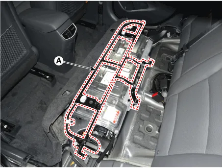
| 5. | Remove the high voltage battery rear cover (A) after loosening the mounting bolts and nuts.
|

| 6. | Remove the inlet cooling duct. (Refer to Hybrid Control System - "Cooling Duct") |
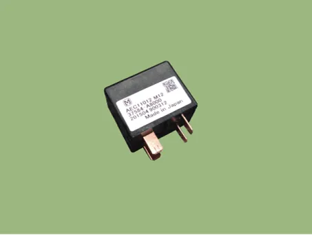
| 7. | Disconnect the pre-charge relay (A).
|

| Installation |
|

| 1. | Install the pre-charge relay in the reverse order of removal.
|
| Inspection |
|
| 1. | Remove the power relay assembly. (High Battery System - "Power Relay Assembly") |
| 2. | Measure the resistance between the PRA connector terminals #6 and #5.
|
| [Use Multi Tester (Relay OFF)] |
| 1. | Shut off the high voltage. (Refer to Hybrid Control System - "High Voltage Shut-off Procedures") |
| 2. | Remove the high voltage battery rear cover. (Refer to High Voltage Battery System - "Case") |
| 3. | Remove the inlet cooling duct. (Refer to Hybrid Control System - "Cooling Duct") |
| 4. | Measure the resistance between the high voltage power terminal (+) and the inverter power terminal (+).
|

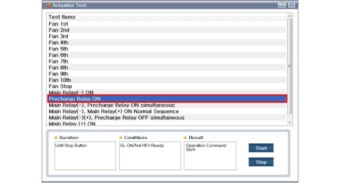
| [GDS - Relay ON] |
| 1. | Connect the GDS to the Data Link Connector (DLC). |
| 2. | Turn the ignition switch ON. |
| 3. | Activate the pre-charge relay by using "Actuation Test" on the GDS as shown in the illustration below.
|

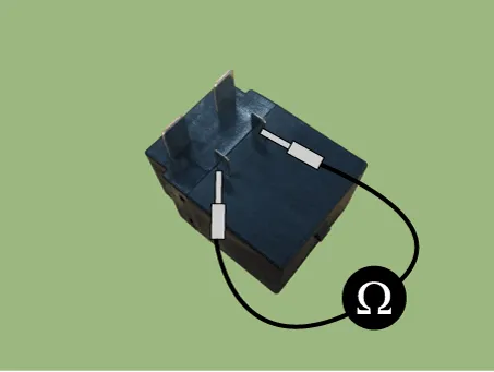
| 1. | Shut off the high voltage. (Refer to Hybrid Control System - "High Voltage Shut-off Procedures") |
| 2. | Remove the power relay assembly. (Refer to High Battery System - "Power Relay Assembly") |
| 3. | Check for continuity between the terminals using an ohmmeter.
|
Circuit Diagram
DescriptionPre-Charge Resistor is integrated into the Power Relay Assembly (PRA). It protects the high voltage circuit by limiting the current while the inverter capacitor is being charged.
Other information:
Hyundai Ioniq (AE) 2017-2022 Service & Repair Manual: Heater Core. Repair procedures
Replacement1.Disconnect the negative (-) battery terminal. 2.Remove the heater and blower assembly.(Refer to Heater - "Heater Unit") 3.Loosen the mounting screws and remove the driver's temperature control actuator (A).4.Remove the heater core cover (A) after loosening the mounting screws.
Hyundai Ioniq (AE) 2017-2022 Service & Repair Manual: Repair procedures
Replacement1.Remove the battery (-) terminal.2.Remove the engine room under cover.(Refer to Engine Mechanical System - "Engine Room Under Cover")3.Remove the heater hose (A) and AEWP hose (B).4.Disconnect the lock pin to remove the heater hose pump connector (A).
Categories
- Manuals Home
- Hyundai Ioniq Owners Manual
- Hyundai Ioniq Service Manual
- DCT(Dual Clutch Transmission) System
- Maintenance
- General Information
- New on site
- Most important about car
