
Hyundai Ioniq (AE): Multifunction Switch / Repair procedures
Hyundai Ioniq (AE) 2017-2022 Service & Repair Manual / Body Electrical System / Multifunction Switch / Repair procedures
| Removal |
| 1. | Disconnect the negative (-) battery terminal. |
| 2. | Remove the steering wheel. (Refer to Steering System - "Steering Wheel") |
| 3. | Remove the steering column upper and lower shrouds after loosening the screws. (Refer to Body - "Steering Column Shroud Panal") |
| 4. | Remove the clock spring. (Refer to Restraint - "Driver Airbag (DAB) Module and Clock Spring") |
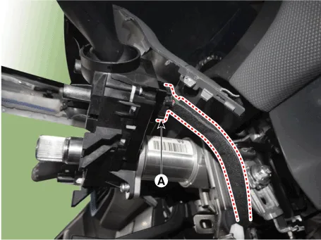
| 5. | Disconnect the multifunction switch connector (A).
|
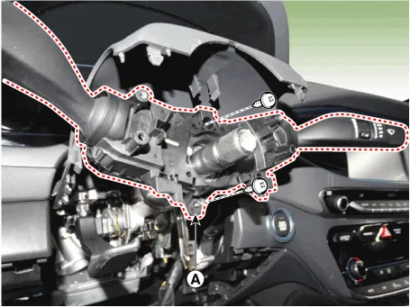
| 6. | Remove the multifunction switch assembly (A) after loosening the screws.
|
| Installation |
| 1. | Install the multifunction switch. |
| 2. | Install the clock spring. |
| 3. | Install the steering column upper and lower shrouds. |
| 4. | Install the steering wheel. |
| 5. | Connect the negative (-) battery terminal. |
| Inspection |
Multifunction Switch Inspection
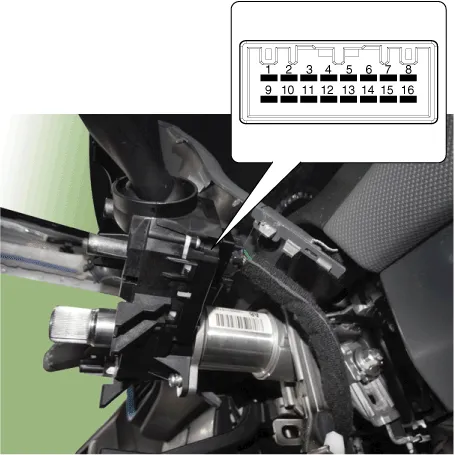
| 1. | Check for continuity between the terminals in each switch position according to the table.
[Left Handle Drive]
[Right Handle Drive]
|
Inspection (with GDS)
| 1. | The body electrocal system can be quickly diagnosed failed parts with vehicle diagnostic system(GDS). The diagnostic system (GDS) provides the following information.
|
| 2. | Select the "Car Model" and the system to be checked in order to check the vehicle with the tester. |
| 3. | Select the "Body Control Module (BCM)" to check the multi function switch. |
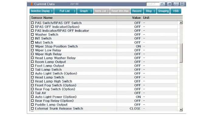
| 4. | Select the "Current Data" menu to search the current state of the input/output data. The input/output data for the sensors corresponding to the multi function switch can be checked.
|
Component1. Steering column2. Multifunction switch3. Screw4. Clock spring
Other information:
Hyundai Ioniq (AE) 2017-2022 Service & Repair Manual: Rear Corner Safety ON/OFF Switch. Repair procedures
Inspection1.Disconnect the negative (-) battery terminal.2.Remove the crash pad lower panel.(Refer to Body - "Crash Pad Lower Panel")3.Remove the lower crash pad switch assembly (A) after disengaging the mounting clip.4.Remove the rheostat switch connector (A).
Hyundai Ioniq (AE) 2017-2022 Service & Repair Manual: Repair procedures
Removal1.Disconnect the negative (-) battery terminal.2.Remove the tailgate lid trim.(Refer to Body - "TailGate Lid Trim")3.Disconnect the Rear view camera connector (A).4.Remove the Rear view camera assembly after loosening the mounting screws.Installation1.
Categories
- Manuals Home
- Hyundai Ioniq Owners Manual
- Hyundai Ioniq Service Manual
- Suspension System
- Components and components location
- Engine Control/Fuel System
- New on site
- Most important about car

Copyright © 2026 www.hioniqae.com - 0.0187