Hyundai Ioniq (AE): Injector / Repair procedures
Hyundai Ioniq (AE) 2017-2022 Service & Repair Manual / Engine Control/Fuel System / Engine Control System / Injector / Repair procedures
| Inspection |
| 1. | Turn the ignition switch OFF. |
| 2. | Disconnect the injector connector. |
| 3. | Measure resistance between the injector terminals 1 and 2. |
| 4. | Check that the resistance is within the specification.
|
| Removal |
|

| 1. | Turn the ignition switch OFF and disconnect the battery negative (-) cable. |
| 2. | Release the residual pressure in fuel line. (Refer to Fuel Delivery System - "Release Residual Pressure in Fuel Line")
|

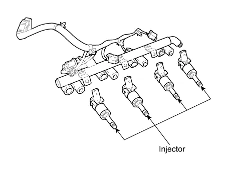
| 3. | Remove the delivery pipe & injector assembly. (Refer to Fuel Delivery System - "Delivery Pipe") |
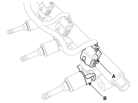
| 4. | Remove the connector (A) and the fixing clip (B), and then separate the injector from the delivery pipe.
|
| Installation |
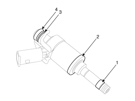
| 1) | Combustion seal |
| 2) | Rubber washer |
| 3) | Support disc |
| 4) | O-ring |
|
|
|
|
|
|
|
| 1. | Install in the reverse order of removal. |
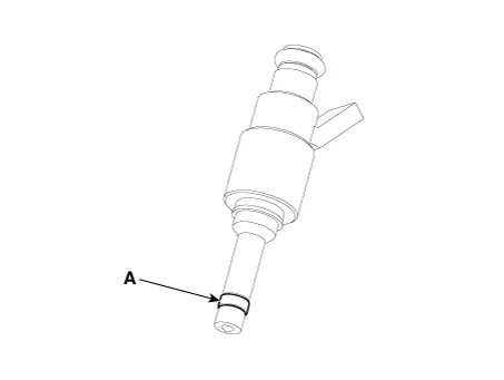
| Replacement |
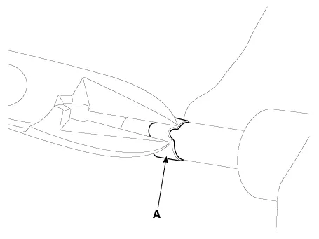
The injector combustion seal should be replaced new one to prevent leakage after removing the injector.
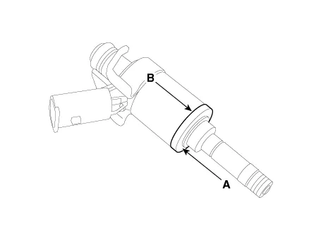
| 1. | Remove the combustion seal (A) with a wire cutter.
|
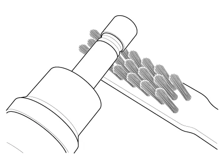
| 2. | Before the assembly of the sealing ring the groove must be cleaned using a clean cloth. Any coking of the injector sealing surface must be carefully removed with a brass-wire brush.
|
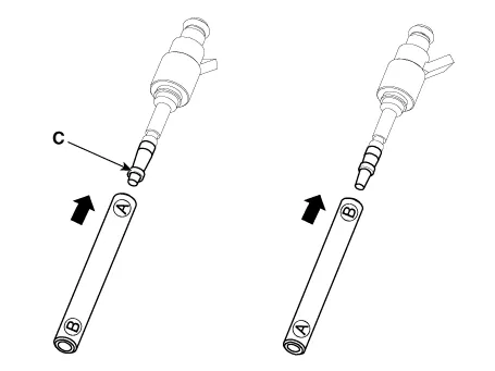
| 3. | Place the seal installing guide (B) (SST No.: 09353-2B000) on the tip of the injector not to damage the injector tip (A). Push the sealing ring (C) with thumb and index finger over the conical assembly tool until it snaps into the groove. The complete assembly must not take longer than 2 to 3 seconds.
|

| 4. | To size the sealing ring the injector is first introduced into the sizing tool (A) (SST No.: 09353-2B000) and then pressed and at the same time rotated 180° into the sizing tool.
|
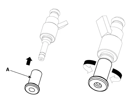
| 5. | Pull the injector out of the sizing tool by turning it in the reverse direction to that used for the press-in process.
|
| 6. | Check the combustion seal (A) installation.
|
Circuit Diagram
DescriptionPurge Control Solenoid Valve (PCSV) is installed on the surge tank and controls the passage between the canister and the intake manifold. It is a solenoid valve and is open when the ECM grounds the valve control line.
Other information:
Hyundai Ioniq (AE) 2017-2022 Service & Repair Manual: Mode Control Actuator. Components and components location
C
Hyundai Ioniq (AE) 2017-2022 Service & Repair Manual: Repair procedures
Removal1.Disconnect the negative (-) battery terminal.2.Remove the tailgate lid trim.(Refer to Body - "TailGate Lid Trim")3.Disconnect the Rear view camera connector (A).4.Remove the Rear view camera assembly after loosening the mounting screws.Installation1.
Categories
- Manuals Home
- Hyundai Ioniq Owners Manual
- Hyundai Ioniq Service Manual
- Engine Clutch System
- Maintenance
- Theft-alarm System
- New on site
- Most important about car

Copyright © 2026 www.hioniqae.com - 0.0209