Hyundai Ioniq (AE): Injector / Schematic diagrams
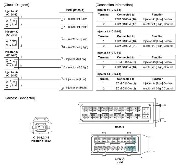
| Circuit Diagram |
Signal WaveformThe three waveforms below are taken from the #1 and #4 injectors. The top waveform is from the high side (feed side) of the #1 and #4 injectors, while the middle waveform is from the low side (ground side) of the #1 injector and the bottom waveform is from the low side of the #4 injector.
Inspection1.Turn the ignition switch OFF.2.Disconnect the injector connector.3.Measure resistance between the injector terminals 1 and 2.4.Check that the resistance is within the specification.
Other information:
Hyundai Ioniq (AE) 2017-2022 Service & Repair Manual: Duct Sensor. Components and components location
C
Hyundai Ioniq (AE) 2017-2022 Service & Repair Manual: Climate Control Air Filter. Repair procedures
Replacement1.Disconnect the air damper (A) from the glove box (B).2.Remove the stopper (B) from the glove box (A).3.Remove the filter cover (A) by pressing the knob.4.Replace the air filter (A) with a new one according to the direction of air filter. • To remove the filter easily, press the right side inwa
Categories
- Manuals Home
- Hyundai Ioniq Owners Manual
- Hyundai Ioniq Service Manual
- DCT(Dual Clutch Transmission) System
- How to Connect Portable Charger (ICCB: In-Cable Control Box)
- Maintenance
- New on site
- Most important about car
