Hyundai Ioniq (AE): Injector / Troubleshooting
Hyundai Ioniq (AE) 2017-2022 Service & Repair Manual / Engine Control/Fuel System / Engine Control System / Injector / Troubleshooting
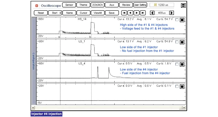
| Signal Waveform |
The three waveforms below are taken from the #1 and #4 injectors. The top waveform is from the high side (feed side) of the #1 and #4 injectors, while the middle waveform is from the low side (ground side) of the #1 injector and the bottom waveform is from the low side of the #4 injector.
The middle waveform is the same as the top waveform because there is no ground for the circuit. With no current flowing in the circuit, the #1 injector is not energized and fuel does not flow.
The bottom waveform shows that ground is supplied and there is a voltage drop across the #4 injector. With current flowing in the circuit, the #4 injector is energized and fuel flows.
Specification Item Specification Coil Resistance (Ω)1.425 - 1.575 [20°C (68°F)]
Circuit Diagram
Other information:
Hyundai Ioniq (AE) 2017-2022 Service & Repair Manual: Front Radar Unit. Repair procedures
Removal1.Remove the front bumper.(Refer to Body - "Front Bumper")2.Disconnect the smart cruise control unit connector (A).3.Remove the smart cruise control nuit assembly (B) from thevehicle after loosening mounting bolts.Installation1.Install in the reverse order of removal.
Hyundai Ioniq (AE) 2017-2022 Service & Repair Manual: Specifications
S
Categories
- Manuals Home
- Hyundai Ioniq Owners Manual
- Hyundai Ioniq Service Manual
- Engine Control/Fuel System
- If the 12 Volt Battery is Discharged (Hybrid Vehicle)
- Engine Mechanical System
- New on site
- Most important about car

Copyright © 2026 www.hioniqae.com - 0.009