Hyundai Ioniq (AE): Input shaft speed sensor 1 / Repair procedures
| Removal |
|

|

| 1. | Shut off the High Voltage circuit. (Refer to General Information - "High Voltage Shutoff Procedure") |
| 2. | Remove the engine room under cover. (Refer to Engine And Transaxle Assembly - "Engine Room Under Cover") |
| 3. | Loosen the drain plug, and drain the inverter coolant. Remove the reservoir cap to help drain the coolant faster. (Refer to Hybrid Motor System - "Coolant") |
| 4. | Remove the HPCU (Hybrid Power Control Unit). (Refer to Hybrid Control System - "Hybrid Power Control Unit (HPCU)") |
| 5. | Remove the ECM (Engine Control Module) and TCM (Transmssion Control Module). (Refer to Engine Control/Fuel System - "Engine Control Module (ECM)") (Refer to Dual Clutch Control System - "DCT Control Module (TCM)") |
| 6. | Remove the HPCU (Hybrid Power Control Unit) tray. (Refer to Hybrid Control System - "Hybrid Power Control Unit (HPCU)") |
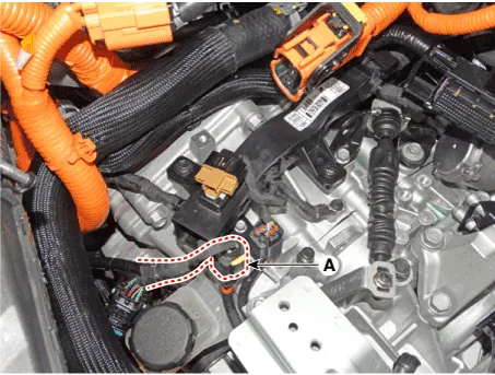
| 7. | Disconnect the input shaft speed sensor connector (A).
|
| 8. | Remove the clutch actuator assembly. (Refer to Dual Clutch Transmission Control System - "Clutch Actuator") |
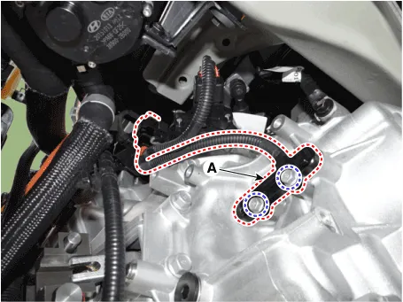
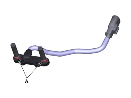
| 9. | Remove the input shaft speed sensor (A).
|
| Installation |
| 1. | Install in the reverse order of removal.
|
Circuit Diagram
Other information:
Hyundai Ioniq (AE) 2017-2022 Service & Repair Manual: Mode Control Actuator. Description and operation
DescriptionThe mode control actuator is located at the heater unit.It adjusts the position of the mode door by operating the mode control actuator based on the signal of the A/C control unit. Pressing the mode select switch makes the mode control actuator shift in order of Vent → Bi-Level → Floor → Mix.
Hyundai Ioniq (AE) 2017-2022 Service & Repair Manual: Intake Actuator. Repair procedures
Inspection1.Turn the ignition switch OFF.2.Disconnect the intake actuator connector.3.Verify that the intake actuator operates to the fresh position when connecting 12V to terminal 3 and grounding terminal 4.Verify that the intake actuator operates to the recirculation position when connected in reverse.
Categories
- Manuals Home
- Hyundai Ioniq Owners Manual
- Hyundai Ioniq Service Manual
- Repair procedures
- Engine Mechanical System
- Maintenance
- New on site
- Most important about car

Copyright © 2026 www.hioniqae.com - 0.013