Hyundai Ioniq (AE): Inhibitor Switch / Repair procedures
| Inspection |
|

| 1. | Inspect DTC code. |
| 2. | Inspect whether N setting matches.
|
| 3. | Inspect shift cable separation.
|
| 4. | Inspect whether connector is connected.
|
| 5. | Inspect ground condition on reversing light circuit.
|
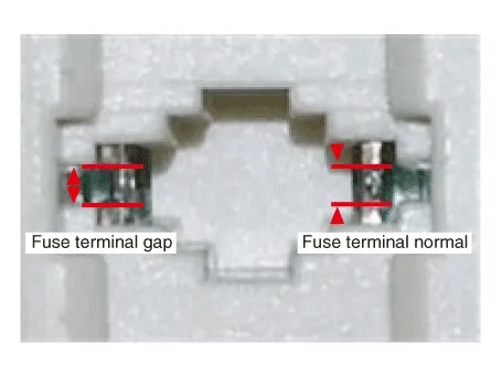
| 6. | Inspect wiring connection on junction box power terminal and fuse lamp.
|

| 7. | Inspect inhibitor switch signal.
|
| Removal |
|

|
| 1. | Shut off the High Voltage circuit. (Refer to General Information - "High Voltage Shutoff Procedure") |
| 2. | Remove the engine room under cover. (Refer to Engine And Transaxle Assembly - "Engine Room Under Cover") |
| 3. | Loosen the drain plug, and drain the inverter coolant. Remove the reservoir cap to help drain the coolant faster. (Refer to Hybrid Motor System - "Coolant") |
| 4. | Remove the HPCU (Hybrid Power Control Unit). (Refer to Hybrid Control System - "Hybrid Power Control Unit (HPCU)") |
| 5. | Remove the ECM (Engine Control Module) and TCM (Transmssion Control Module). (Refer to Engine Control/Fuel System - "Engine Control Module (ECM)") (Refer to Dual Clutch Control System - "DCT Control Module (TCM)") |
| 6. | Remove the HPCU (Hybrid Power Control Unit) tray. (Refer to Hybrid Control System - "Hybrid Power Control Unit (HPCU)") |
| 7. | Make sure vehicle does not roll before setting shift lever to "N" position. |
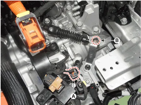
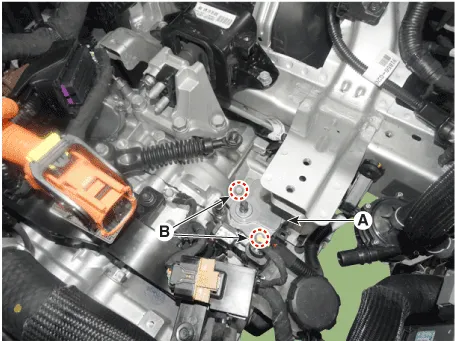
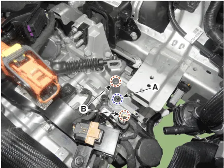
| 8. | Disconnect the inhibitor switch extension connector (A). |
| 9. | Remove the shift cable mounting nut (B).
|
| 10. | Remove the manual control lever (A) and the washer after removing a nut (B).
|
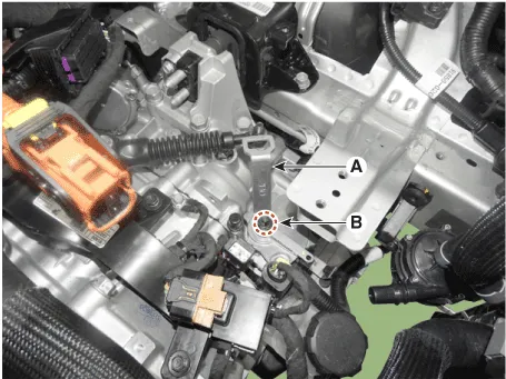
| 11. | Remove the inhibitor assembly (A) after removing the bolts (B-2ea).
|
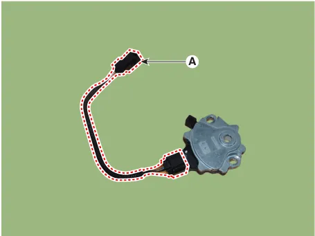
| 12. | Remove the extension connector (A) from the inhibitor switch
|
| Installation |
| 1. | Check that the shift lever is placed in the "N" position. |
| 2. | Lightly tighten the inhibitor switch mounting bolts (B) after installing the inhibitor switch (A).
|
| 3. | Lightly tighten the manual control lever mounting nut (B) after installing the manual control lever (A).
|
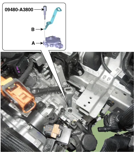
| 4. | Align the hole (A) in the manual control lever with the "N" position hole (B) of the inhibitor switch and then insert the inhibitor switch guide pin (SST No.:09480-A3800).
|
| 5. | Tighten the manual lever mounting nut (A) to the specified torque.
|
| 6. | Tighten the inhibitor switch mounting bolts (B) to the specified torque.
|
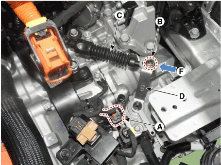
| 7. | Lightly tighten the nut (B) after connected the shift cable (C) in the manual control lever (D). |
| 8. | Tighten the nut (B) after Push shift cable (C) lightly to "F" direction shown to eliminate free play of shift cable.
|
| 9. | Connect the inhibitor switch connector (A).
|
| 10. | Remove the inhibitor switch guide pin (SST No. : 09480-A3800) from the hole. |
| 11. | Install the engine room under cover. (Refer to Engine Mechanical System - "Engine Room Under Cover") |
| 12. | Install the HPCU (Hybrid Power Control Unit) tray. (Hybrid Control System - "HPCU") |
| 13. | Install the ECM (Engine Controm Module) and TCM (Transmission Control Module) (Refer to Engine Control/Fuel System - "ECM") (Refer to Dual Clutch Control System - "TCM") |
| 14. | Install the HPCU (Hybrid Power Control Unit). (Hybrid Control System - "HPCU") |
| 15. | Bleed air from the hybrid motor cooling system using the GDS. (Refer to Hybrid Motor System- "Coolant")
|

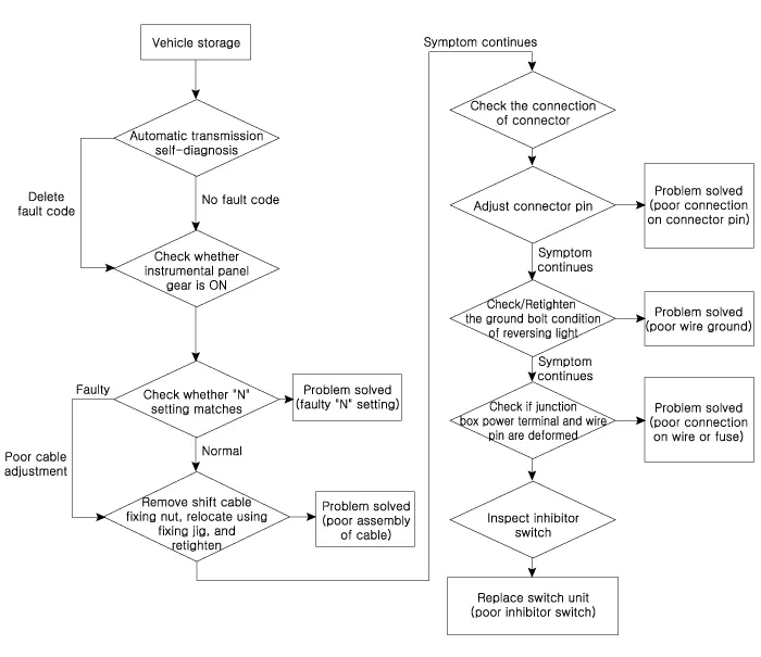
Fault DiagnosisFault Diagnosis for Symptom Major Symptom Expected Cause Items to Check and Measures Shift lever not operating Gear not marked on cluster Shock occurs while shifting lever Warning lamp ON Engine OFF while vehicle is parked Inhibitor switch circuit abnormalInhibitor switch function abnormalCheck the inspection FLOW and replace the inhibitor switchInhibitor switch "N" setting faultyAdjust "N" setting using "N" setting jig (Refer to Dual Clutch Transmission Control System - "Inhibitor Switch")Shift cable separation faultyAdjust shift cable separation (Refer to Dual Clutch Transmission Control System - "Inhibitor Switch")Poor ground condition on reversing light circuitCheck the ground condition on reversing light and retighten itInhibitor switch vehicle side circuit abnormal Check the connection of junction box power terminal, fuse (TCU) terminal and replace the junction box or adjust the gapCheck inside the inhibitor switch connector for foreign substance and whether terminal is bentPoor ground condition on inhibitor switch wireCheck the ground condition of wire and retighten itPoor inhibitor unit (disconnection/short-circuit)Replace inhibitor switch (refer to inhibitor switch inspection)
Components1. Shift lever knob & boots assembly2. Shift lever assembly3. Shift cable4. Manual control lever5. Shift cable retainer
Other information:
Hyundai Ioniq (AE) 2017-2022 Service & Repair Manual: Blower Unit. Repair procedures
Replacement When prying with a flat-tip screwdriver or use a prying trim tool, wrap it with protective tape, and apply protective tape around the related parts, to prevent damage.1.Disconnect the negative (-) battery terminal.2.Recover the refrigerant with a recovery / recycling / charging station.
Hyundai Ioniq (AE) 2017-2022 Service & Repair Manual: Front Radar Unit. Repair procedures
Removal1.Remove the front bumper.(Refer to Body - "Front Bumper")2.Disconnect the smart cruise control unit connector (A).3.Remove the smart cruise control nuit assembly (B) from thevehicle after loosening mounting bolts.Installation1.Install in the reverse order of removal.
Categories
- Manuals Home
- Hyundai Ioniq Owners Manual
- Hyundai Ioniq Service Manual
- Heating, Ventilation and Air Conditioning
- Theft-alarm System
- If the 12 Volt Battery is Discharged (Hybrid Vehicle)
- New on site
- Most important about car
