Hyundai Ioniq (AE): Dual Clutch Transmission Control System / Shift Lever. Components and components location
Hyundai Ioniq (AE) 2017-2022 Service & Repair Manual / DCT(Dual Clutch Transmission) System / Dual Clutch Transmission Control System / Shift Lever. Components and components location
| Components |
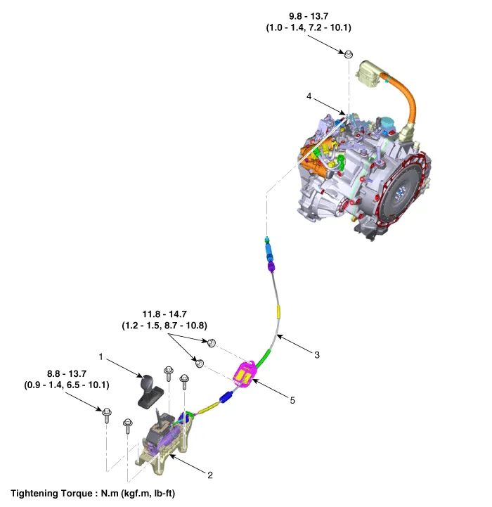
| 1. Shift lever knob & boots assembly 2. Shift lever assembly 3. Shift cable | 4. Manual control lever 5. Shift cable retainer |
Inspection • Thoroughly check connectors for looseness, poor connection, bending, corrosion, contamination, deterioration, or damage.
Removal 1.Remove the shift lever knob & boots (A) pull both of it up. 2.Remove the floor console assembly.(Refer to Body - "Floor Console")3.Disconnect the connector (A).
Other information:
Hyundai Ioniq (AE) 2017-2022 Service & Repair Manual: Auto Defoging Actuator. Specifications
S
Hyundai Ioniq (AE) 2017-2022 Service & Repair Manual: Schematic diagrams
Trouble Symptom ChartsComponent Parts and Function Outline Component part Function Cruise Control Switch Input the set speed and distance to the SCC ECU. Instrument Cluster Display various information inputted from SCC.
Categories
- Manuals Home
- Hyundai Ioniq Owners Manual
- Hyundai Ioniq Service Manual
- Brake System
- Engine Mechanical System
- Jump starting procedure
- New on site
- Most important about car

Copyright © 2026 www.hioniqae.com - 0.0147