Hyundai Ioniq (AE): Dual Clutch Transmission Control System / Shift Cable. Repair procedures
Hyundai Ioniq (AE) 2017-2022 Service & Repair Manual / DCT(Dual Clutch Transmission) System / Dual Clutch Transmission Control System / Shift Cable. Repair procedures
| Removal |
|

|

| 1. | Shut off the High Voltage circuit. (Refer to General Information - "High Voltage Shutoff Procedure") |
| 2. | Remove the engine room under cover. (Refer to Engine And Transaxle Assembly - "Engine Room Under Cover") |
| 3. | Loosen the drain plug, and drain the inverter coolant. Remove the reservoir cap to help drain the coolant faster. (Refer to Hybrid Motor System - "Coolant") |
| 4. | Remove the HPCU (Hybrid Power Control Unit). (Refer to Hybrid Control System - "Hybrid Power Control Unit (HPCU)") |
| 5. | Remove the ECM (Engine Control Module) and TCM (Transmssion Control Module). (Refer to Engine Control/Fuel System - "Engine Control Module (ECM)") (Refer to Dual Clutch Control System - "DCT Control Module (TCM)") |
| 6. | Remove the HPCU (Hybrid Power Control Unit) tray. (Refer to Hybrid Control System - "Hybrid Power Control Unit (HPCU)") |
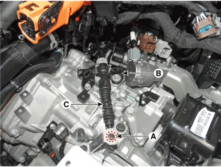
| 7. | Disconnect the gear actuator motor connector (A) and solenoid connector (B).
|
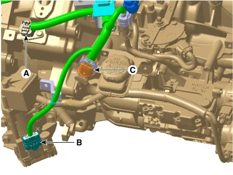
| 8. | Disconnect the hybrid motor connector (A) and engine clutch actuator connector (B). |
| 9. | Disconnect the DCT clutch actuator connector (C).
|
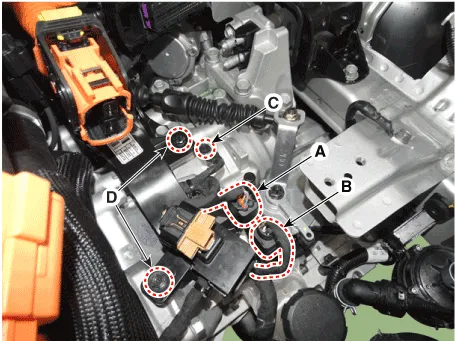
| 10. | Disconnect the inhibitor switch connector (A) and input shaft speed sensor connector (B). |
| 11. | Remove the ground bolt (C) and wiring bracket bolt (D).
|
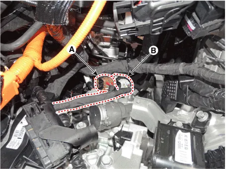
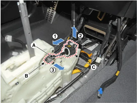
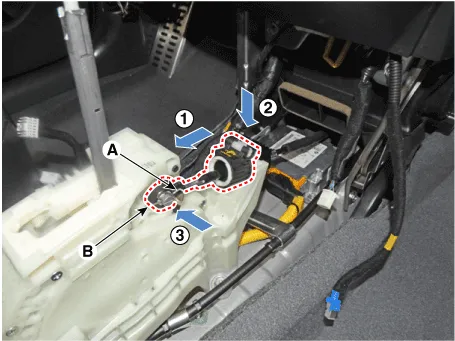
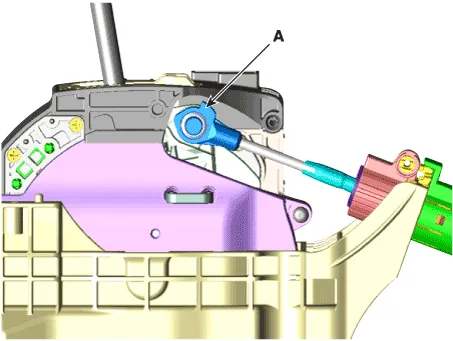
| 12. | Remove the shift cable (C) from the cable bracket (B), after loosening the mounting nut (A).
|
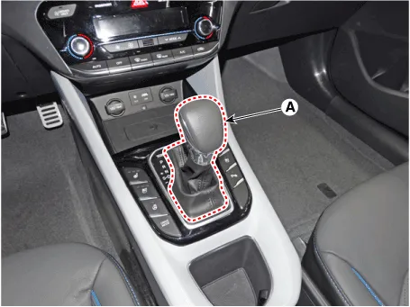
| 13. | Remove the shift lever knob & boots (A) pull both of it up.
|
| 14. | Remove the floor console assembly. (Refer to Body - "Floor Console") |
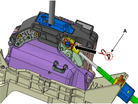
| 15. | Disconnect the shift cable.
|
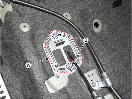
| 16. | Remove the retainer (A) by loosening the nuts (B-2ea).
|
| 17. | Remove the shift cable from the vehicle. |
| Installation |
| 1. | Install the retainer (A) and then tighten the nut (B-2ea).
|
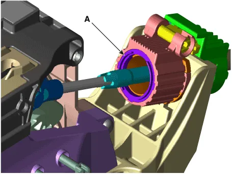
| 2. | Install the shift cable (B) and then fix the snap pin (A).
|

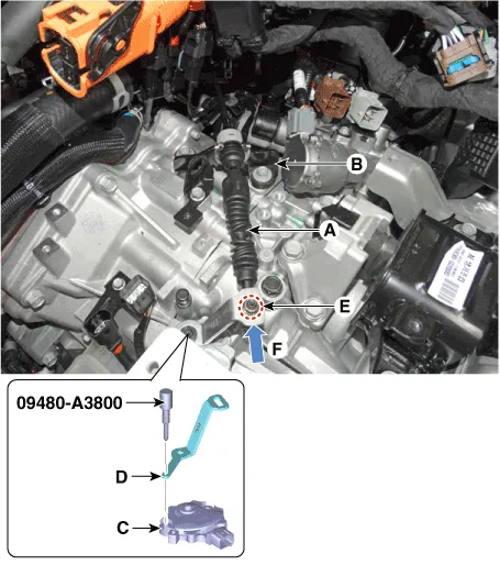
| 3. | Install the shift cable (A) in the cable bracket (B). |
| 4. | Align the hole (C) in the manual control lever with the "N" position hole (D) of the inhibitor switch and then insert the inhibitor switch guide pin (SST No. : 09480-A3800). |
| 5. | Lightly tighten the nut (E) after connected the shift cable (B) in the manual control lever. |
| 6. | Tighten the nut (E) after Push shift cable (B) lightly to "F" direction shown to eliminate free play of shift cable.
|
| 7. | Remove the inhibitor switch guide pin (SST No. : 09480-A3800) from the hole. |
| 8. | Install the engine room under cover. (Refer to Engine Mechanical System - "Engine Room Under Cover") |
| 9. | Install the HPCU (Hybrid Power Control Unit) tray. (Hybrid Control System - "HPCU") |
| 10. | Install the ECM (Engine Controm Module) and TCM (Transmission Control Module) (Refer to Engine Control/Fuel System - "ECM") (Refer to Dual Clutch Control System - "TCM") |
| 11. | Install the HPCU (Hybrid Power Control Unit). (Hybrid Control System - "HPCU") |
| 12. | Bleed air from the hybrid motor cooling system using the GDS. (Refer to Hybrid Motor System- "Coolant") |
| 13. | Install the floor console assembly. (Refer to Body - "Floor Console")
|
Components1. Shift lever knob & boots assembly2. Shift lever assembly3. Shift cable4. Manual control lever5. Shift cable retainer
Other information:
Hyundai Ioniq (AE) 2017-2022 Service & Repair Manual: emperature Control Actuator. Specifications
S
Hyundai Ioniq (AE) 2017-2022 Service & Repair Manual: Front View Camera Unit. Repair procedures
Removal1.Disconnect the negative (-) battery terminal.2.Remove the front view camera cover (A).3.Disconnect the front view camera connector (A).4.Remove the front view camera after disengaging the mounting bracket (A).Installation1.Align front view camera with windshield bracket using forward edge point (A).
Categories
- Manuals Home
- Hyundai Ioniq Owners Manual
- Hyundai Ioniq Service Manual
- Repair procedures
- Checking the Coolant Level
- Jump starting procedure
- New on site
- Most important about car

Copyright © 2026 www.hioniqae.com - 0.0131