
Hyundai Ioniq (AE): Audio / Audio Remote Control. Schematic diagrams
Hyundai Ioniq (AE) 2017-2022 Service & Repair Manual / Body Electrical System / Audio / Audio Remote Control. Schematic diagrams
| Circuit Diagram |
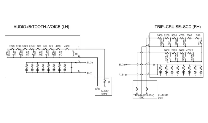
[Audio+B/Tooth]
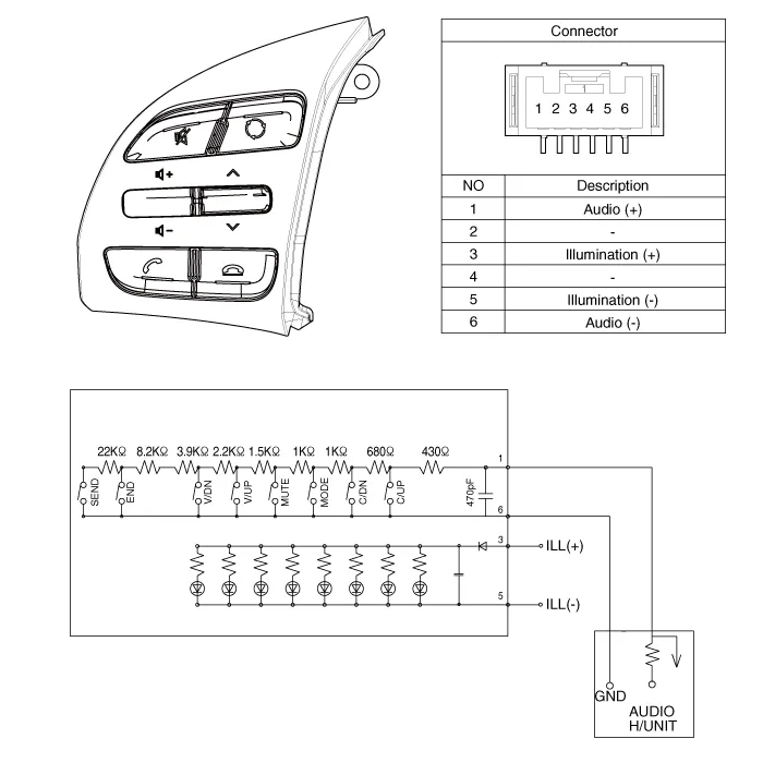
[Audio+B/Tooth+Voice]
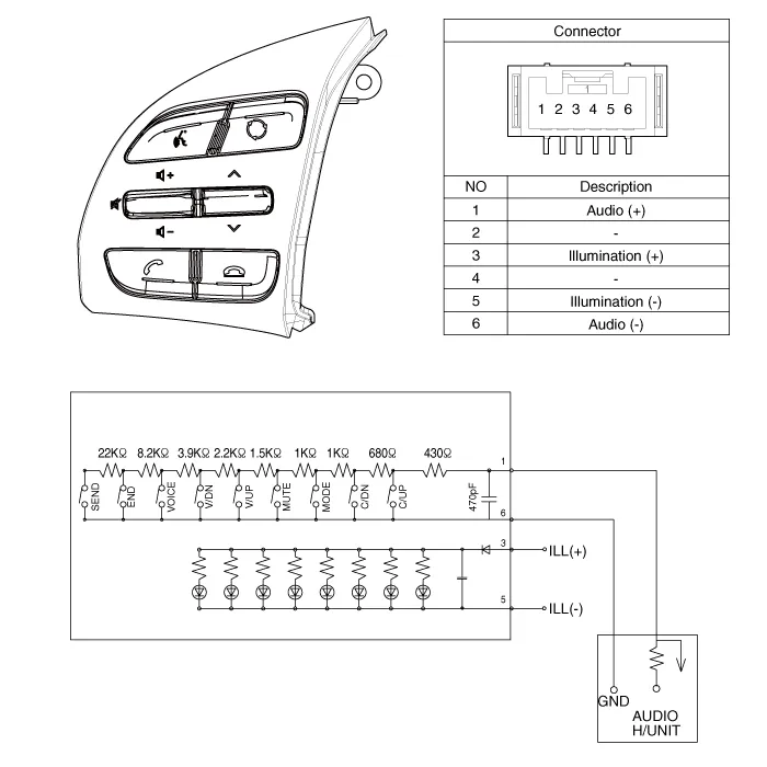
[Trip]
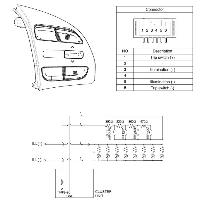
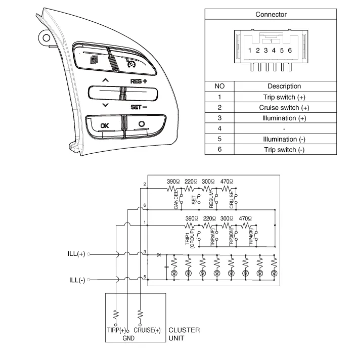
[Trip+Cruise]
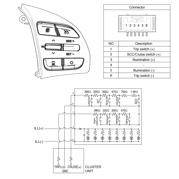
[Trip+Cruise+SCC]
Components1. Left Remote Control Switch (Audio + Hands free)2. Right Remote Control Switch(Cruise+Trip Computer)
Inspection1.Check for resistance between terminals in each switch position (LH).[LH : Audio+B/TOOTH+VOICE] Switch Connector terminal Resistance (±5%) SEEK Up1-6430 ΩSEEK Down1.
Other information:
Hyundai Ioniq (AE) 2017-2022 Service & Repair Manual: In-car Sensor. Repair procedures
Diagnosis With GDS1.The heating, ventilation and air conditioning can be quickly diagnosed failed parts with vehicle diagnostic system (GDS).※ The diagnostic system (GDS) provides the following information.(1) Self diagnosis : Checking the failure code (DTC) and display.
Hyundai Ioniq (AE) 2017-2022 Service & Repair Manual: Components and components location
C
Categories
- Manuals Home
- Hyundai Ioniq Owners Manual
- Hyundai Ioniq Service Manual
- Hybrid Control System
- Hybrid Vehicle Engine Compartment
- Troubleshooting
- New on site
- Most important about car

Copyright © 2026 www.hioniqae.com - 0.0162