
Hyundai Ioniq (AE): Cooling System / Cooling Fan. Components and components location
| Components |
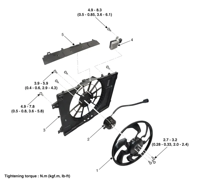
| 1. Cooling fan 2. Fan motor 3. Cooling fan shroud | 4. Cooling fan controller (PWM) 5. Cooling fan upper guard |
Engine Coolant Refilling and Bleeding [Drain] • Never remove the reservoir tank cap when the engine is hot.• Serious scalding could be caused by hot fluid under high pressure escaping from the radiator.
Specifications Items Performance spec Fan type PULLER Fan speed control PWM Air flow rate [m³/h (yd³/h)] 2,150 - 8% min.
Other information:
Hyundai Ioniq (AE) 2017-2022 Service & Repair Manual: A/C Pressure Transducer. Description and operation
DescriptionThe A/C Pressure Transducer (APT) converts the pressure value of high pressure line into voltage value after measuring it. By converted voltage value, engine ECU controls the cooling fan by operating it high speed or low speed. Engine ECU stops the operation of the compressor when the temperature of refrigerant line is very high or very
Hyundai Ioniq (AE) 2017-2022 Service & Repair Manual: Heater Unit. Components and components location
Component Location1. Heater unit assemblyCompoents1. Heater core cover2. Heater core & Seal assembly3. Mode actuator [LH]4. Temperature control actuator [LH]5. Shower duct [LH]6. Duct sensor [Floor]7. PTC Heater8. Duct sensor [Vent]9. Heater & Evaporator lower case10.
Categories
- Manuals Home
- Hyundai Ioniq Owners Manual
- Hyundai Ioniq Service Manual
- Jump Starting
- Description and operation
- Repair procedures
- New on site
- Most important about car
