Hyundai Ioniq (AE): Cylinder Block / Crankshaft. Repair procedures
Hyundai Ioniq (AE) 2017-2022 Service & Repair Manual / Engine Mechanical System / Cylinder Block / Crankshaft. Repair procedures
| Disassembly |
|

|

|

| 1. | Remove the engine assembly from the vehicle. (Refer to Engine and Transaxle Assembly - "Engine and Transaxle Assembly") |
| 2. | Remove the transaxle assembly from the engine assembly. (Refer to Double Clutch Transmission (DCT) System - "Double Clutch Transmission (DCT)") |
| 3. | Remove the flywheel. (Refer to Cylinder Block - "Flywheel") |
| 4. | Remove the rear oil seal. (Refer to Cylinder Block - "Rear Oil Seal") |
| 5. | Install the engine to engine stand for disassembly. |
| 6. | Remove the intake manifold. (Refer to Intake and Exhaust System - "Intake Manifold") |
| 7. | Remove the exhaust manifold. (Refer to Intake and Exhaust System - "Exhayst Manifold") |
| 8. | Remove the hybrid starter generator (HSG). (Refer to Hybrid Motor System - "Hybrid Starter Generator (HSG)") |
| 9. | Remove the timing chain. (Refer to Timing System - "Timing Chain") |
| 10. | Remove the cylinder head assembly. (Refer to Cylinder Head Assembly - "Cylinder Head") |
| 11. | Remove the thermostat. (Refer to Cooling System - "Thermostat") |
| 12. | Remove the EGR cooler. (Refer to Intake and Exhaust System - "EGR Cooler") |
| 13. | Remove the A/C compressor. (Refer to Heating, Ventilation Air conditioning -"Compressor") |
| 14. | Remove the knock sensor. (Refer to Engine Control / Fuel System - "Knock Sensor") |
| 15. | Remove the oil pan and oil screen. (Refer to Lubrication System - "Oil Pan") |
| 16. | Remove the ladder frame. (Refer to Cylinder Block - "Piston and Connecting Rod") |
| 17. | Remove the piston and connecting rod assemblies. (Refer to Cylinder Block - "Piston and Connecting Rod") |
| 18. | Remove the main bearing caps and check oil clearance. |
| 19. | Check the crankshaft end play. |
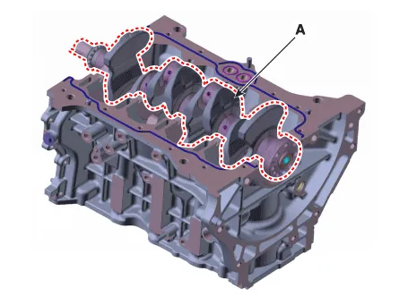
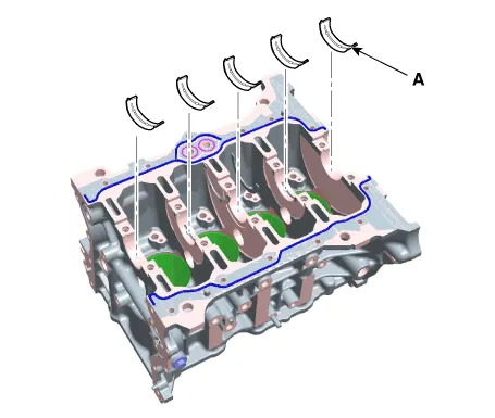
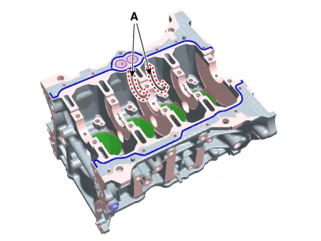
| 20. | Lift the crankshaft (A) out of engine, being careful not to damage journals.
|
| Inspection |
| 1. | Check the crankshaft bearing oil clearance.
| |||||||||||||||||||||||||||||||||||||||||||||||||||||||||||||||||||||||||||||||||||||||||||||||||||
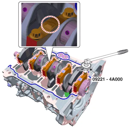
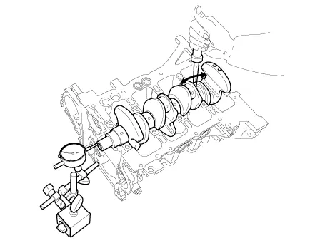
| 2. | Check crankshaft end play. Using a dial indicator, measure the thrust clearance while prying the crankshaft back and forth with a screwdriver.
If the end play is greater than maximum, replace the center bearings as a set. |
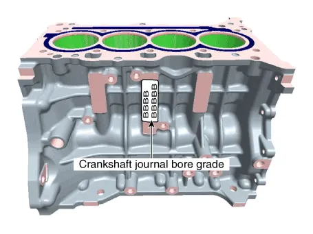
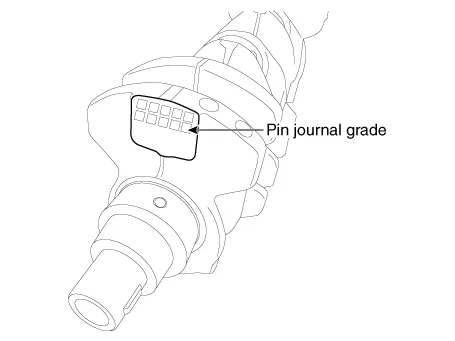
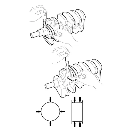
| 3. | Inspect the crankshaft main journals and pin journals. Using a micrometer, measure the diameter of each main journal and pin journal.
|
| Reassembly |
|
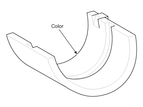
| 1. | Install the crankshaft main bearings.
|
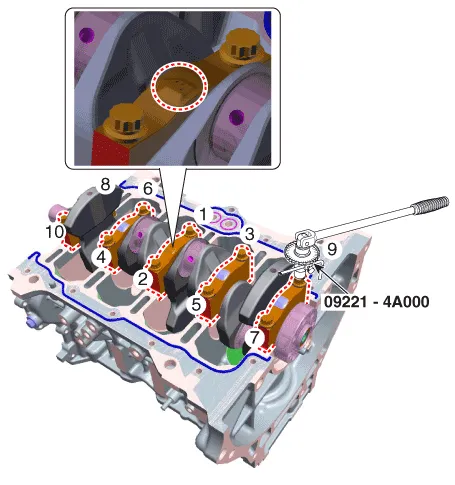
| 2. | Place the crankshaft (A) on the cylinder block.
|
| 3. | Install the main bearing cap (A).
|
| 4. | Check the crankshaft end play. |
| 5. | Assemble the other parts in the reverse order of disassembly. |
Components1. Thrust bearing2. Main bearing (Upper)3. Crankshaft4. Main bearing (Lower)5. Main bearing cap
Disassembly • Be sure to read and follow the "General Safety Information and Caution" before doing any work related with the high voltage system.
Other information:
Hyundai Ioniq (AE) 2017-2022 Service & Repair Manual: emperature Control Actuator. Specifications
S
Hyundai Ioniq (AE) 2017-2022 Service & Repair Manual: Smart Cruise Control (SCC) Switch. Repair procedures
Removal1.Disconnect the negative (-) battery terminal.2.Remove the steering wheel assembly.(Refer to Steering System -"Steering Wheel")3.Remove the steering back cover (A).4.Remove the steering remote control connector (A).5.Remove the steering remote control (A), after loosening the screws.
Categories
- Manuals Home
- Hyundai Ioniq Owners Manual
- Hyundai Ioniq Service Manual
- General Information
- Maintenance
- Child-Protector Rear Door Locks
- New on site
- Most important about car

Copyright © 2026 www.hioniqae.com - 0.0211