Hyundai Ioniq (AE): Cylinder Head Assembly / CVVT & Camshaft. Components and components location
Hyundai Ioniq (AE) 2017-2022 Service & Repair Manual / Engine Mechanical System / Cylinder Head Assembly / CVVT & Camshaft. Components and components location
| Components |
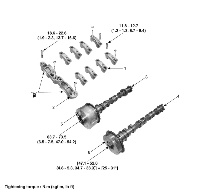
| 1. Camshaft bearing cap 2. Front camshaft bearing cap 3. Exhaust camshaft | 4. Intake camshaft 5. Exhaust CVVT assembly 6. Intake CVVT assembly |
Removal • Use fender covers to avoid damaging painted surfaces. • To avoid damage, unplug the wiring connectors carefully while holding the connector portion.
DescriptionThe continuous variable valve timing (CVVT) system advances or retards the opening of an intake or exhaust valve according to the ECM signals that are determined based on engine RPM and load.
Other information:
Hyundai Ioniq (AE) 2017-2022 Service & Repair Manual: emperature Control Actuator. Components and components location
C
Hyundai Ioniq (AE) 2017-2022 Service & Repair Manual: Intake Actuator. Repair procedures
Inspection1.Turn the ignition switch OFF.2.Disconnect the intake actuator connector.3.Verify that the intake actuator operates to the fresh position when connecting 12V to terminal 3 and grounding terminal 4.Verify that the intake actuator operates to the recirculation position when connected in reverse.
Categories
- Manuals Home
- Hyundai Ioniq Owners Manual
- Hyundai Ioniq Service Manual
- Front Disc Brake. Repair procedures
- Maintenance
- Brake System
- New on site
- Most important about car

Copyright © 2026 www.hioniqae.com - 0.0201