Hyundai Ioniq (AE): Cylinder Head Assembly / CVVT & Camshaft. Description and operation
Hyundai Ioniq (AE) 2017-2022 Service & Repair Manual / Engine Mechanical System / Cylinder Head Assembly / CVVT & Camshaft. Description and operation
| Description |
The continuous variable valve timing (CVVT) system advances or retards the opening of an intake or exhaust valve according to the ECM signals that are determined based on engine RPM and load.
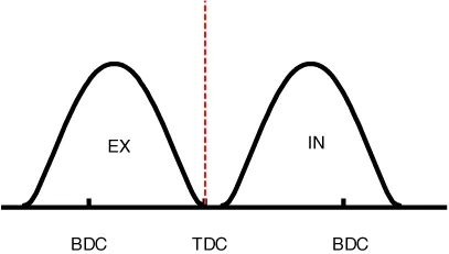
Due to CVVT control, a valve overlap or underlap occurs between the intake valve and exhaust valve, resulting in the reduction of pumping loss, recirculation of exhaust gas, improvement in combustion stability and volumetric efficiency, and increase in expansion work. This in turn improves fuel efficiency and engine performance and reduces emission gases (NOx and HC).
The CVVT system is composed of a CVVT oil control valve (OCV), CVVT oil temperature sensor (OTS), and a cam phaser; The OCV receives a pulse width modulation signal from the ECM and controls the flow of oil to supply oil to the cam phaser, the OTS measures the temperature of the engine oil, and the cam phaser changes the phase of the camshaft using the engine oil pressure.
The oil supplied from the CVVT OCV rotates the rotor connected to the camshaft inside the cam phaser. The rotor, in turn, rotates the camshaft in the direction of engine rotation (intake advanced / exhaust retarded) or in the opposite direction of engine rotation (intake retarded / exhaust advanced) to change the phase angle of the cam.

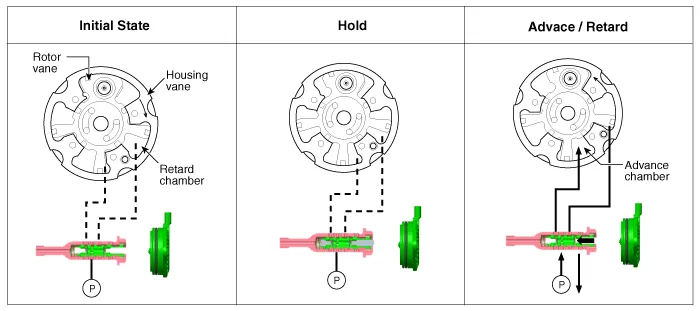
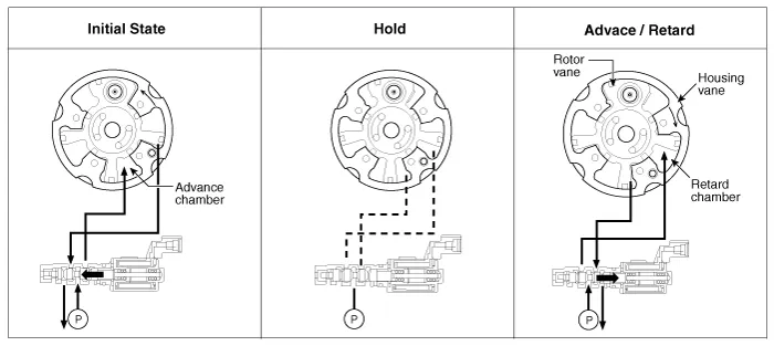
| Operation Principle |
The CVVT has the mechanism rotating the rotor vane with hydraulic force generated by the engine oil supplied to the advance or retard chamber in accordance with the CVVT oil control valve control.
|

| 1. | Intake CVVT
|
| 2. | Exhaust CVVT
|
| [CVVT System Mode] |
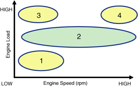
| (1) Low Speed / Low Load | (2) Part Load |
|
|
| (3) Low Speed / High Load | (4) High Speed / High Load |
|
|
| Driving Condition | Exhaust Valve | Intake Valve | ||
| Valve Timing | Effect | Valve Timing | Effect | |
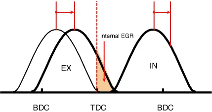
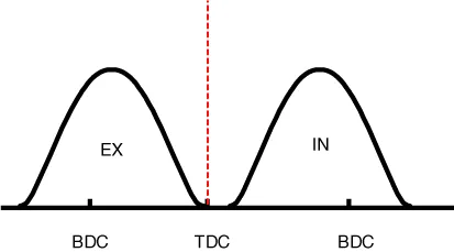
| (1) Low Speed /Low Load | Completely Advance | * Valve Under-lap * Improvement of combustion stability | Middle | * Valve Under-lap * Improvement of combustion stability |
| (2) Part Load | Retard | * Reduction of HC | Retard | * Delays the closing time of intake valve to reduce pumping loss |
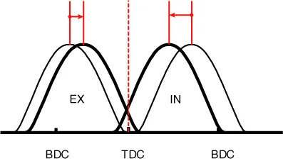
| (3) Low Speed /High Load | Completely Advance | * Reduction of pumping loss | Advance | * Improvement of volumetric efficiency |
| (4) High Speed /High Load | Completely Advance | * Reduction of pumping loss | Advance | * Improvement of volumetric efficiency |
Components1. Camshaft bearing cap2. Front camshaft bearing cap3. Exhaust camshaft4. Intake camshaft5. Exhaust CVVT assembly6. Intake CVVT assembly
Removal ŌĆó Be sure to read and follow the ŌĆ£General Safety Information and CautionŌĆØ before doing any work related with the high voltage system.
Other information:
Hyundai Ioniq (AE) 2017-2022 Service & Repair Manual: Climate Control Air Filter. Repair procedures
Replacement1.Disconnect the air damper (A) from the glove box (B).2.Remove the stopper (B) from the glove box (A).3.Remove the filter cover (A) by pressing the knob.4.Replace the air filter (A) with a new one according to the direction of air filter. ŌĆó To remove the filter easily, press the right side inwa
Hyundai Ioniq (AE) 2017-2022 Service & Repair Manual: Components and components location
C
Categories
- Manuals Home
- Hyundai Ioniq Owners Manual
- Hyundai Ioniq Service Manual
- General Information
- Transmission Gear Oil. Repair procedures
- Brake System
- New on site
- Most important about car

Copyright ┬® 2026 www.hioniqae.com - 0.0147