Hyundai Ioniq (AE): Cylinder Head Assembly / Cylinder Head Cover. Repair procedures
| Removal |
|

|

| 1. | Disconnect the battery negative terminal. |
| 2. | Remove the air cleaner assembly. (Refer to Intake and Exhaust System - "Air Cleaner") |
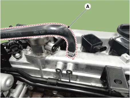
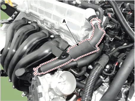
| 3. | Disconnect the breather hose (A).
|
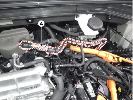
| 4. | Disconnect the fuel hose (A).
|
| 5. | Disconnect the reservoir tank coolant hose. (Refer to Cooling System - "Reservoir Tank") |
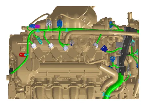
| 6. | Disconnect the wiring connectors and harness clamps and remove the connector brackets around the cylinder head cover.
|
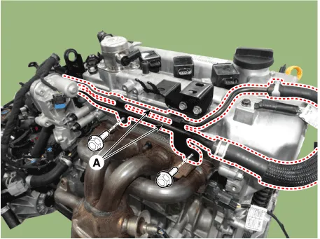
| 7. | Remove the reservoir tank coolant pipe (A).
|
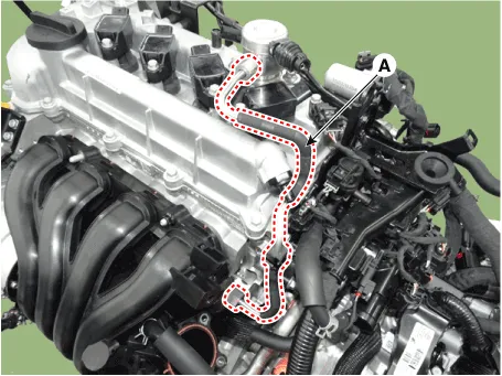
| 8. | Disconnect the positive crankcase ventilation (PCV) hose (A).
|
| 9. | Remove the high pressure fuel pipe (A).
|
| 10. | Remove the high pressure fuel pump. (Refer to Engine Control / Fuel System - "High Pressure Fuel Pump") |
| 11. | Remove the ignition coils. (Refer to Engine Electrical System - "Ignition Coil") |
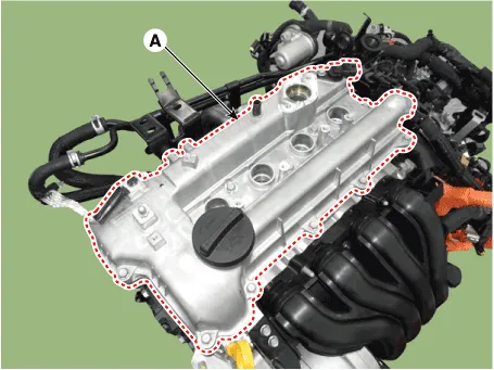
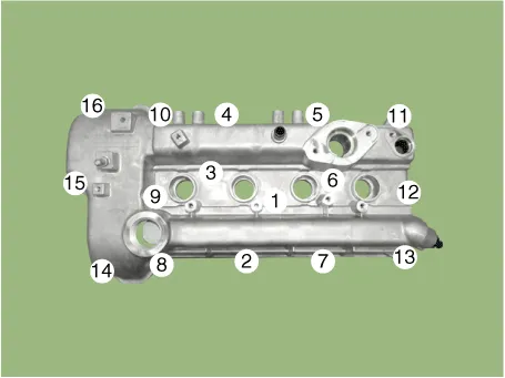
| 12. | Remove the cylinder head cover (A).
|
| Installation |
| 1. | Install the cylinder head cover.
|
| 2. | Install the other parts in the reverse order of removal. |
Components1. Cylinder head cover2. Cylider head cover gasket3. Camshaft position sensor
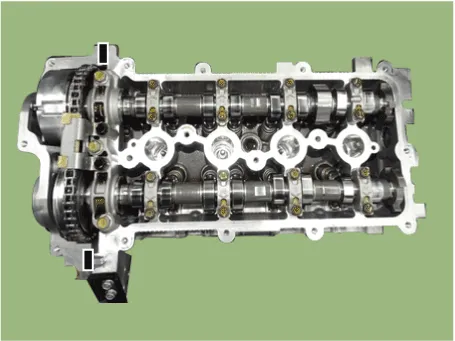
Components1. Camshaft bearing cap2. Front camshaft bearing cap3. Exhaust camshaft4. Intake camshaft5. Exhaust CVVT assembly6. Intake CVVT assembly
Other information:
Hyundai Ioniq (AE) 2017-2022 Service & Repair Manual: In-car Sensor. Repair procedures
Diagnosis With GDS1.The heating, ventilation and air conditioning can be quickly diagnosed failed parts with vehicle diagnostic system (GDS).※ The diagnostic system (GDS) provides the following information.(1) Self diagnosis : Checking the failure code (DTC) and display.
Hyundai Ioniq (AE) 2017-2022 Service & Repair Manual: Description and operation
DescriptionRear corner radar is a system that uses two magnetic wave radar sensors attached on the rear panel to measure the distance from the following vehicles and provides the sensing and (visual and auditory) alarm of any vehicle coming into the blind spot.
Categories
- Manuals Home
- Hyundai Ioniq Owners Manual
- Hyundai Ioniq Service Manual
- Checking the Coolant Level
- Engine Mechanical System
- Transmission Gear Oil. Repair procedures
- New on site
- Most important about car
