Hyundai Ioniq (AE): Electric A/C Compressor / Schematic diagrams
| Connector Configurations |
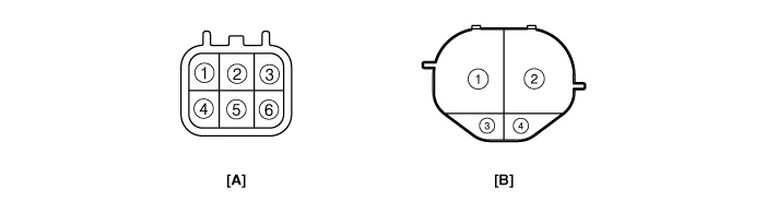
| Terminal Function |
|
Connector
|
Pin No.
|
Function
|
| A | 1 | 12V Power Ground |
| 2 | Climate CAN Low | |
| 3 | Interlock (-) | |
| 4 | 12V Power | |
| 5 | Climate CAN High | |
| 6 | Interlock (+) | |
| B | 1 | High Voltage Power |
| 2 | High Voltage Ground | |
| 3 | Compressor Interlock (-) | |
| 4 | Compressor Interlock (+) |
Components Location1. Electric A/C CompressorComponents1. Electric A/C Compressor inverter assembly2. Gasket3. Electric A/C Compressor body assembly
Troubleshooting
Other information:
Hyundai Ioniq (AE) 2017-2022 Service & Repair Manual: Parking Distance Warning (PDW) Sensor. Repair procedures
Removal1.Disconnect the negative (-) battery terminal.2.Remove the front / rear bumper cover.(Refer to Body - "Front Bumper Cover")(Refer to Body - "Rear Bumper Cover")3.Disconnect the connector (A) from the parking assist sensor.4.Remove the sensor (A) by pulling out both ends of the sensor holder.
Hyundai Ioniq (AE) 2017-2022 Service & Repair Manual: Schematic diagrams
System Block DiagramComponent Parts and Function Outline Component part Function Vehicle-speed sensor, ESP/ABS Control ModuleConverts vehicle speed to pulse.VCUReceives signals from sensor and control switches.
Categories
- Manuals Home
- Hyundai Ioniq Owners Manual
- Hyundai Ioniq Service Manual
- DCT(Dual Clutch Transmission) System
- Front Disc Brake. Repair procedures
- Jump Starting
- New on site
- Most important about car

Copyright © 2026 www.hioniqae.com - 0.0133