Hyundai Ioniq (AE): Dual Clutch Transmission Assembly / DCT (Dual Clutch Transmission). Repair procedures
| Removal |
|

|

| 1. | Shut off the High Voltage circuit. (Refer to General Information - "High Voltage Shutoff Procedure") |
| 2. | Remove the engine room under cover. (Refer to Engine And Transaxle Assembly - "Engine Room Under Cover") |
| 3. | Loosen the drain plug, and drain the inverter coolant. Remove the reservoir cap to help drain the coolant faster. (Refer to Hybrid Motor System - "Coolant") |
| 4. | Remove the HPCU (Hybrid Power Control Unit). (Refer to Hybrid Control System - "Hybrid Power Control Unit (HPCU)") |
| 5. | Remove the ECM (Engine Control Module) and TCM (Transmssion Control Module). (Refer to Engine Control/Fuel System - "Engine Control Module (ECM)") (Refer to Dual Clutch Control System - "DCT Control Module (TCM)") |
| 6. | Remove the HPCU (Hybrid Power Control Unit) tray. (Refer to Hybrid Control System - "Hybrid Power Control Unit (HPCU)") |
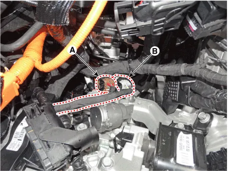
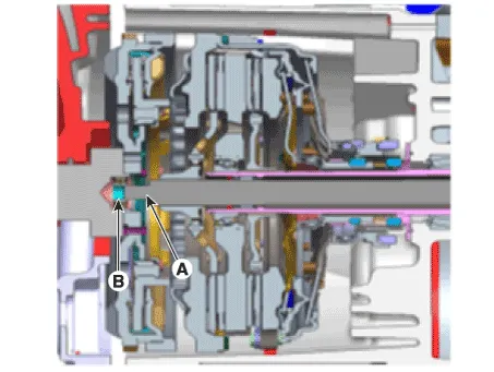
| 7. | Disconnect the gear actuator motor connector (A) and solenoid connector (B).
|
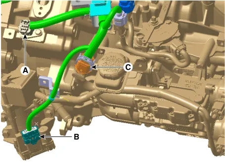
| 8. | Disconnect the hybrid motor connector (A) and engine clutch actuator connector (B). |
| 9. | Disconnect the DCT clutch actuator connector (C).
|
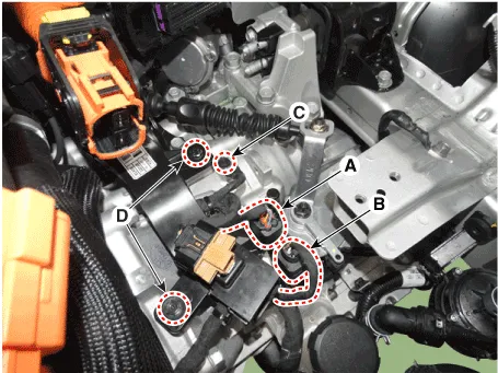
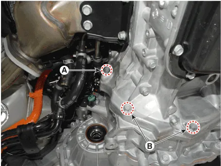
| 10. | Disconnect the inhibitor switch connector (A) and input shaft speed sensor connector (B). |
| 11. | Remove the ground bolt (C) and wiring bracket bolt (D).
|
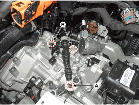
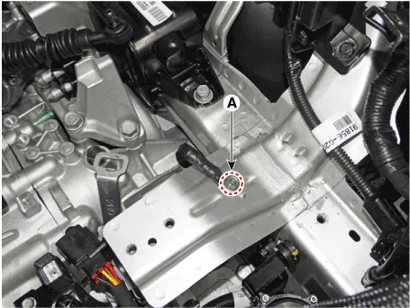
| 12. | Remove the nut (A) and shift cable bracket bolt (B-2ea).
|
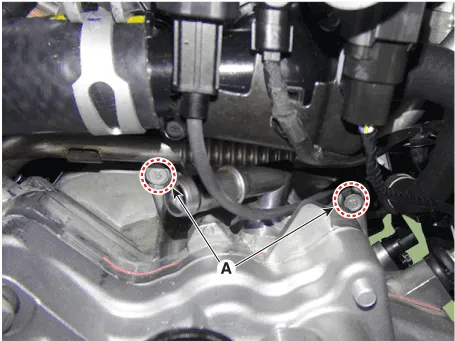
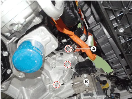
| 13. | Remove the ground bolts (A).
|
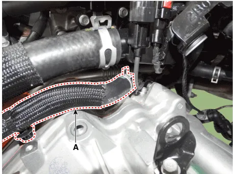
| 14. | Remove the hybrid motor cooling hose (A).
|
| 15. | Remove the hybrid motor upper mounting bolt (A-3ea).
|
| 16. | Assemble the engine support fixture (beam No.: 09200-38001 or 09200-3N000, supporter No.: 09200-2S000). (Refer to Special Service Tools - "Engine Support Fixture Assembly Drawing") |
| 17. | Using the engine support fixture(A), hold the engine and transaxle assembly safely.
|

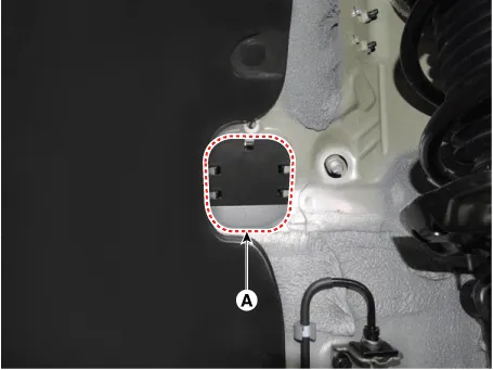
| 18. | Remove the dust cover (A).
|
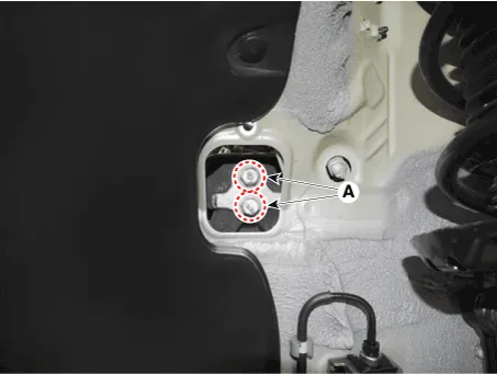
| 19. | Remove the transmission support bracket mounting bolt (A-2ea).
|
| 20. | Remove the transmission support bracket (A).
|
| 21. | Remove the sub frame. (Refer to Suspension System - "Sub Frame") |
| 22. | Remove the front drive shaft assembly. (Refer to Driveshaft and Axle - "Front Driveshaft") |
| 23. | Remove the AWEP (Auxiliary Electronic water pump). (Refer to Heating, Ventilation and Air Conditioning - "AWEP (Auxiliary Electronic water pump)") |
| 24. | Remove the crankshaft position sensor. (Engine Control / Fuel System - "Crankshaft Position Sensor (CKPS)") |
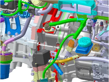
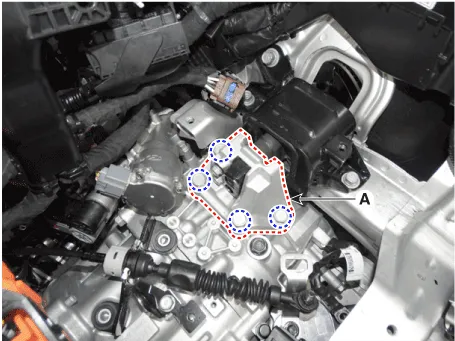
| 25. | Remove the roll rod support bracket (A).
|
| 26. | Support the hybrid motor and transmission safely by using the jack. |
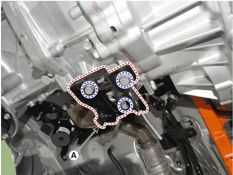
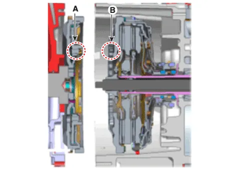
| 27. | Remove the hybird motor lower mounting bolts (A, B).
|
| 28. | After separating the hybrid motor and transmission from the engine, remove the transmission by lowering the jack slowly.
|

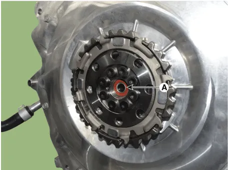
| 29. | Remove the hybrid motor assembly from the dual clutch transmission. |
| Installation |
| 1. | Install in the reverse order of removal.
|
| 2. | Observe each separate procedure below for reinstallation or replacement with a new dual clutch transmission. |
| 1. | If the differential oil seal is damaged and oil is leaking, replace the oil seal with a new one. When installing a new oil seal, use the special tool (09430-C1190, 09231-H1100). |
| 2. | After installing the DCT, check the oil level after refilling the DCT with oil. (Refer to Dual Clutch Transmission System - "Transmission Gear oil") |
| 3. | Bleed air from the hybrid motor cooling system using GDS. (Refer to Hybrid Motor System- "Coolant") |
| 4. | Clear the diagnostic trouble codes (DTC) using the KDS/GDS. Disconnecting the battery negative terminal will not clear the DTCs. Clear the DTCs using the KDS/GDS at all times. |
| 1. | After replacing the new DCT, it need not oil refill & level check procedure because oil is already filled with specified quantity inside new DCT. |
| 2. | Clear the diagnostic trouble codes (DTC) using the KDS/GDS. Disconnecting the battery negative terminal will not clear the DTCs. Clear the DTCs using the KDS/GDS at all times. |
| 3. | Bleed air from the hybrid motor cooling system using the GDS. (Refer to Hybrid Motor System- "Coolant") |
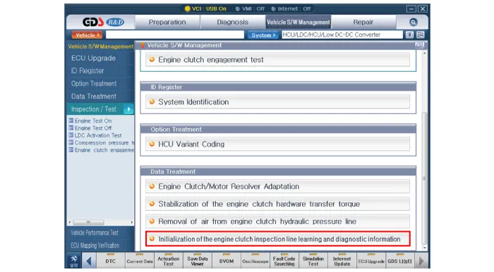
| 4. | Perform initialization of the engine clutch inspection line learning and diagnostic information using the GDS.
|
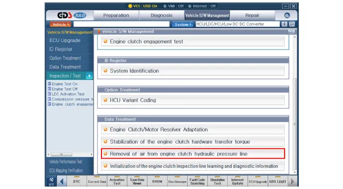
| 5. | Perform of the removal of air from engine clutch hydraulic pressure line using the GDS.
|
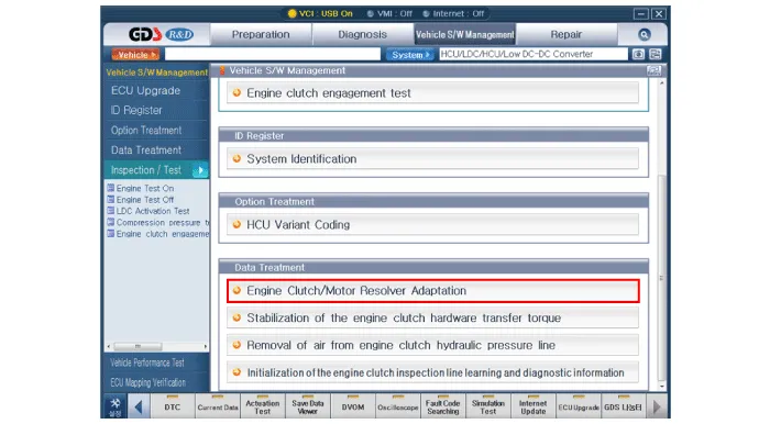
| 6. | Perform of the engine clutch/motor resolver adaptation using the GDS.
|
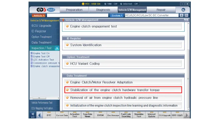
| 7. | Perform of the stabilization of the engine clutch hardware transfer torque using the GDS.
|
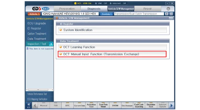
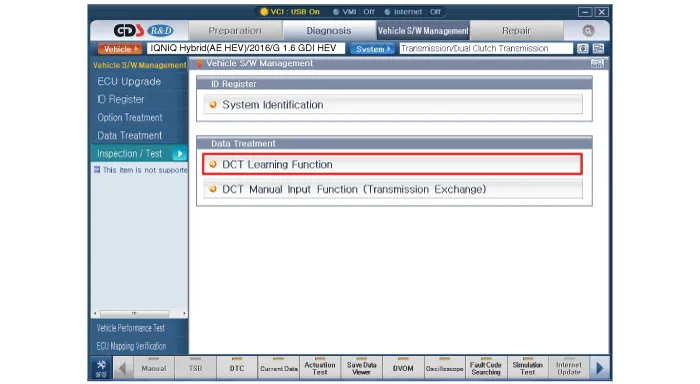
| 8. | Perform clutch characteristics input procedure using the GDS. (One of two procedures must be performed.)
|
Components (1)1. Dual clutch transmission assembly2. Hybrid motor assembly3. Gear actuator4. Clutch actuator5. Engine clutch actuator6. Reserver7. Dust cover8.
General Information1.Check & Change intervals Check & Replenishment Change Capacity Oil specification Normal Use Severe Use No checkNo service required120000 km( 80000 miles)1.
Other information:
Hyundai Ioniq (AE) 2017-2022 Service & Repair Manual: Description and operation
DescriptionThe smart cruise control system allows a driver to program the vehicle to control the speed and following distance by detecting the vehicle ahead without depressing the brake pedal and the accelerator pedal.1.Cruise speed control : The vehicle maintains the selected speed if there are not vehicles ahead.
Hyundai Ioniq (AE) 2017-2022 Service & Repair Manual: Repair procedures
Diagnosis with GDS1.REAR CORENER RADAR system defects can be quickly diagnosed with the GDS. GDS operates actuator quickly to monitor, input/output value and self diagnosis.2.Connect the cable of GDS to the data link connector in driver side crash pad lower panel, turn the power on GDS.
Categories
- Manuals Home
- Hyundai Ioniq Owners Manual
- Hyundai Ioniq Service Manual
- DCT(Dual Clutch Transmission) System
- Theft-alarm System
- Brake System
- New on site
- Most important about car
