Hyundai Ioniq: Trip Computer / Digital speedometer, Drive Info display

Hyundai Ioniq (AE) 2017-2025 Owner's Manual / Convenient features of your vehicle / Trip Computer / Digital speedometer, Drive Info display

Digital speedometer

Hyundai Ioniq. Digital speedometer, Drive Info display

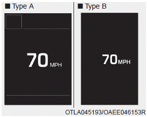
This message shows the speed of the vehicle.

Drive Info display

Hyundai Ioniq. Digital speedometer, Drive Info display

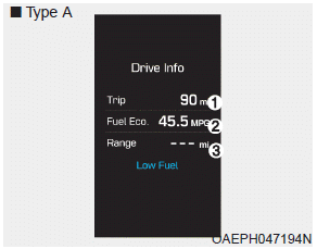
At the end of each driving cycle, the Driving Info message is displayed. This display shows the trip distance (1), the average fuel economy (2), and the remaining vehicle range (3).

This information is displayed for a few seconds when you turn off the ignition, and then goes off automatically. The information is calculated for each ignition cycle.

If the estimated remaining vehicle range is below 1 mi. (1 km), the distance to empty will display as "----" and a "Low Fuel" warning message (4) will be displayed.

Information

If sunroof open warning is displayed in the cluster, the Driving Info message will not be displayed.

    Tripmeter/Average vehicle speed/ Timer

    Tripmeter (1) The tripmeter is the total driving distance since the last tripmeter reset. To reset the tripmeter, press the OK button on the steering wheel for more than 1 second when the tripmeter is displayed...

    Driving style, Energy flow, Engine coolant temperature

    Driving style Energy flow The hybrid system informs the drivers its energy flow in various operating modes. While driving, the current energy flow is specified in 11 modes...

    Other information:

    Hyundai Ioniq (AE) 2017-2025 Service Manual: Engine Control Module (ECM). Schematic diagrams


    ECM Terminal and Input / Output SignalECM Terminal FunctionConnector [C100-A] Pin No Description Connected to 1Injector (Cylinder #3) [Low] control outputInjector (Cylinder #3)2Injector (Cylinder #4) [High] control outputInjector (Cylinder #4)3Injector (Cylinder #3) [Low] control outputInjector (Cylinder #3)4Vehicle speed signal outputCluster5EGR Valve (Motor -)EGR Valve6Sensor power (+5V)Throttle Position Sensor (TPS) 1, 27Sensor power (+5V)EGR Valve8Knock Sensor (KS) signal inputKnock Sensor (KS)9Camshaft Position Sensor (CMPS) [Bank 1 / Exhaust] signal inputCamshaft Position Sensor (CMPS) [Bank 1 / Exhaust]10-11Brake Switch [test] signal inputBrake Switch12Brake Switch [lamp] signal inputBrake Switch13-14-15-16Injector (Cylinder #3) [High] control outputInjector (Cylinder #3)17Injector (Cylinder #1) [High] control outputInjector (Cylinder #1)18Injector (Cylinder #1) [Low] control outputInjector (Cylinder #1)19-20EGR Valve (Motor +)EGR Valve21Sensor shieldKnock Sensor (KS)22Sensor groundKnock Sensor (KS)23-24Sensor groundCamshaft Position Sensor (CMPS) [Bank 1 / Exhaust]25-26-27-28-29-30-31Injector (Cylinder #2) [High] control outputInjector (Cylinder #2) 32-33ETC Motor [-] control outputETC Motor34Sensor groundThrottle Position Sensor (TPS) 1, 235Throttle Position Sensor (TPS) 1 signal inputThrottle Position Sensor (TPS) 136Sensor groundRail Pressure Sensor (RPS)37Rail Pressure Sensor (RPS) signal inputRail Pressure Sensor (RPS)38-39Camshaft Position Sensor (CMPS) [Bank 1 / Intake] signal inputCamshaft Position Sensor (CMPS) [Bank 1 / Intake]40-41-42-43VS-/IP- (Common Ground for VS, IP)Heated Oxygen Sensor [Bank 1 / Sensor 1] 44Rc (Compensative Resistance)Heated Oxygen Sensor [Bank 1 / Sensor 1] 45Sensor groundHeated Oxygen Sensor [Bank 1 / Sensor 2] 46Injector (Cylinder #2) [Low] control outputInjector (Cylinder #2)47-48ETC Motor [+] control outputETC Motor49-50Throttle Position Sensor (TPS) 2 signal inputThrottle Position Sensor (TPS) 251Sensor power (+5V)Rail Pressure Sensor (RPS)52Electrical load signal inputWiper Motor53Sensor groundCamshaft Position Sensor (CMPS) [Bank 1 / Intake]54Sensor groundEGR valve55EGR valve (Feedback signal)EGR valve56-57-58VS+ (NERNST Cell Voltage)Heated Oxygen Sensor [Bank 1 / Sensor 1] 59Rc/Rp (Pump Cell Voltage)Heated Oxygen Sensor [Bank 1 / Sensor 1] 60Heated Oxygen Sensor [Bank 1 / Sensor 2] signal inputHeated Oxygen Sensor [Bank 1 / Sensor 2] Connector [C100-K] Pin No Description Connected to 1ECM GroundChassis Ground2Battery power (B+)Main Relay3ECM GroundChassis Ground4Battery power (B+)Main Relay5ECM GroundChassis Ground6Battery power (B+)Main Relay7Fuel Pressure Control Valve [High] control outputFuel Pressure Control Valve8-9-10Engine Coolant Temperature Sensor (ECTS) signal [EGR Cooler Tube]Engine Coolant Temperature Sensor (ECTS) [EGR Cooler Tube]11Sensor groundEngine Coolant Temperature Sensor (ECTS) [EGR Cooler Tube]12Vehicle speed signal inputIntegrated brake actuation unitSmart key Control Module13-14-15Accelerator Position Sensor (APS) 2 signal inputAccelerator Position Sensor (APS) 216Sensor power (+5V) Accelerator Position Sensor (APS) 217Sensor power (+5V) Manifold Absolute Pressure Sensor (MAPS)18Sensor power (+5V) Accelerator Position Sensor (APS) 119Accelerator Position Sensor (APS) signal inputAccelerator Position Sensor (APS) 120Sensor power (+5V) Crankshaft Position Sensor (CKPS) A/C Pressure Transducer (APT)21-22-23-24Fuel Pump Relay control outputFuel Pump Relay25-26-27-28-29Fuel Pressure Control Valve [Low] control outputFuel Pressure Control Valve30A/C Pressure Transducer (APT) signal inputA/C Pressure Transducer (APT)31-32Crankshaft Position Sensor (CKPS) signal inputCrankshaft Position Sensor (CKPS) 33-34-35-36-37Sensor groundAccelerator Position Sensor (APS) 238Manifold Absolute Pressure Sensor (MAPS) signal inputManifold Absolute Pressure Sensor (MAPS)39Intake Air Temperature Sensor (IATS) signal inputIntake Air Temperature Sensor (IATS)40Sensor groundManifold Absolute Pressure Sensor (MAPS)41Sensor groundAccelerator Position Sensor (APS) 142-43-44Mass Air Flow Sensor (MAFS) signal inputMass Air Flow Sensor (MAFS) 45Sensor groundMass Air Flow Sensor (MAFS) 46Engine Control Relay control outputMain Relay47CVVT Oil control solenoid (OCS) [Bank 1 / Intake] control outputCVVT Oil control solenoid (OCS) [Bank 1 / Intake]48-49-50-51Battery power (B+)Ignition Switch52-53-54Sensor groundCrankshaft Position Sensor (CKPS) 55P-CAN [High]Other control module, Data Link Connector (DLC), Multi-Purpose Check Connetor56H-CAN [High]Other control module, Data Link Connector (DLC), Multi-Purpose Check Connetor57-58Immobilizer communication lineSmart key Control Module59-60Engine Coolant Temperature Sensor (ECTS) signal input [Water Temperature Control Assembly]Engine Coolant Temperature Sensor (ECTS) [Water Temperature Control Assembly]61Sensor groundEngine Coolant Temperature Sensor (ECTS) [Water Temperature Control Assembly]62Fuel Level Sender (FLS) signal inputFuel Level Sender (FLS)63-64Ignition Coil (Cylinder #2) control outputIgnition Coil (Cylinder #2)65Ignition Coil (Cylinder #3) control outputIgnition Coil (Cylinder #3)66-67-68Cooling Fan Relay control outputCooling Fan Relay69-70CVVT Oil Control (OCV) Valve [Bank 1 / Exhaust] control outputCVVT Oil Control Valve (OCV) [Bank 1 / Exhaust] 71- 72- 73Battery power (B+)Battery74- 75Sensor groundA/C Pressure Transducer (APT)76LIN communication signal inputBattery Sensor77P-CAN [Low]Other control module, Data Link Connector (DLC), Multi-Purpose Check Connetor78H-CAN [Low]Other control module, Data Link Connector (DLC), Multi-Purpose Check Connetor79- 80- 81- 82- 838485- 86Ignition Coil (Cylinder #4) control outputIgnition Coil (Cylinder #4)87Ignition Coil (Cylinder #1) control outputIgnition Coil (Cylinder #1)88- 89- 90-91Heated Oxygen Sensor (HO2S) [Bank 1 / Sensor1] Heater control outputHeated Oxygen Sensor (HO2S) [Bank 1 / Sensor 1]92Heated Oxygen Sensor (HO2S) [Bank 1 / Sensor2] Heater control outputHeated Oxygen Sensor (HO2S) [Bank 1 / Sensor 1]93Purge Control Solenoid Valve (PCSV) control outputPurge Control Solenoid Valve (PCSV)94-ECM Terminal Input/Output Signal Connector [C100-A] Pin No Description Condition Type Level 1IInjector (Cylinder #3) [Low] control outputRelay OFFDC71VRelay ONMax 1...

    Hyundai Ioniq (AE) 2017-2025 Service Manual: Side Impact Sensor (SIS). Description and operation


    Description• Side Impact Sensors (SIS), each installed on the center part of the right and left front door modules and the right and left center pillars, detects side impact during collision.• The SRSCM uses the signals from SIS during side collision to determine whether and when to deploy the side air bag...

    Categories

    Air Bag Warning Labels

    Hyundai Ioniq. Air Bag Warning Labels

    Air bag warning labels, required by the U.S. National Highway Traffic Safety Administration (NHTSA), are attached to alert the driver and passengers of potential risks of the air bag system. Be sure to read all of the information about the air bags that are installed on your vehicle in this Owners Manual.

    read more


    Copyright © 2025 www.hioniqae.com