Hyundai Ioniq (AE): Emergency Call System / Emergency Call (eCall) Unit. Repair procedures
Hyundai Ioniq (AE) 2017-2022 Service & Repair Manual / Body Electrical System / Emergency Call System / Emergency Call (eCall) Unit. Repair procedures
| Removal |
You must make sure turn RED LED ON if you do any of the following.
|

| 1. | Disconnect the negative (-) battery terminal. |
| 2. | Remove the floor console assembly. (Refer to Body - "Floor Console Assembly") |
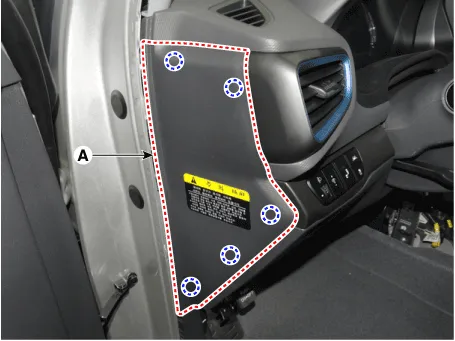
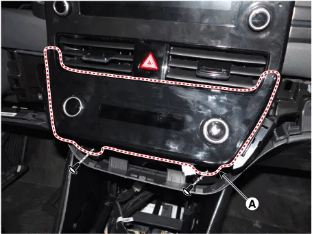
| 3. | Remove the crash pad side cover [LH] (A) by using a remover.
|
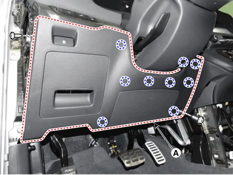
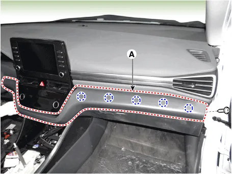
| 4. | Loosen the mounting screws and remove the crash pad lower panel (A).
|
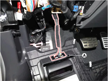
| 5. | Press the lock pin and separate the diagnosis connector (A)
|
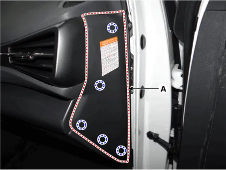
| 6. | Remove the crash pad side cover [RH] (A) by using a remover.
|
| 7. | Loosen the mounting screw and remove the crash pad center garnish (A).
|
| 8. | Loosen the mounting screws and remove the A/C & heater controller unit (A).
|
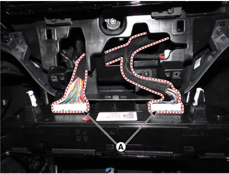
| 9. | Press the lock pin and separate the A/C & heater controller unit connectors (A).
|
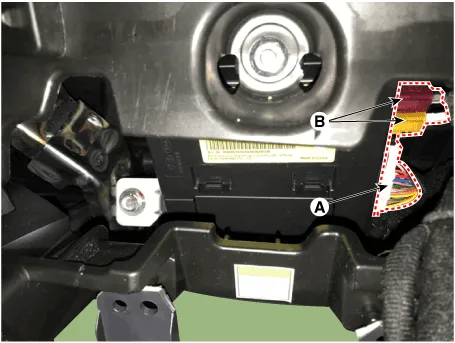
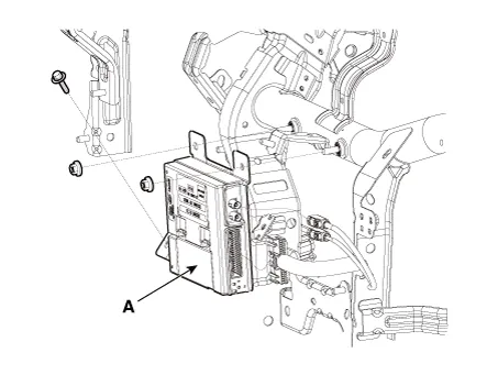
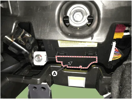
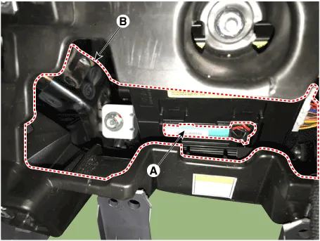
| 10. | Disconnect the ecall unit connector (A) and antenna connectors (B)
|
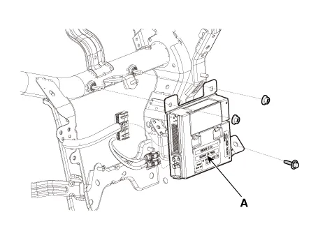
| 11. | Loosen the mounting bolts and nuts and remove the e-call unit (A) towards the console. [LHD]
[RHD]
|
| Replacement |
e-Call Unit Back Up Battery (BUB)
[LHD]
| 1. | Disconnect the negative (-) battery terminal. |
| 2. | Remove the eCall Unit. |
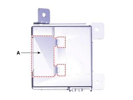
| 3. | If it is necessary to replace the back-up battery, remove the back-up battery cover (A).
|
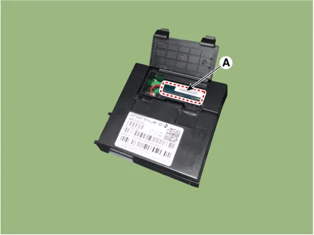
| 4. | Replace the back-up battery (A).
|
[RHD]
| 1. | Disconnect the negative (-) battery terminal. |
| 2. | Remove the crash pad side cover [RH] (A) by using a remover.
|
| 3. | Loosen the mounting screw and remove the crash pad center garnish (A).
|
| 4. | Loosen the mounting screws and remove the A/C & heater controller unit (A).
|
| 5. | Press the lock pin and separate the A/C & heater controller unit connectors (A).
|
| 6. | Disconnect the ecall unit back battery (BUB) service cover (A).
|
| 7. | Replace the back-up battery (A) through service space (B).
|
| Installation |
If RED LED is on, check the eCall system with the diagnostic tools.
|
eCall Unit
| 1. | Install the eCall unit. |
| 2. | Install the main crash pad assembly. |
| 3. | Connect the negative (-) battery terminal. |
| 4. | Perform the "eCall Parameter Download" (Refer to Inspection - " Inspection with Diagnostic Tools") |
| Inspection |
Inspecting Back-Up Battery
Back-up battery (BUB) embedded in the eCall system has a finite lifespan and using it for a long time may decrease its charging/discharging performance.
The back-up battery guarantees the operation of the eCall system when the vehicle battery cannot be used due to an accident. Be sure to inspect the back-up battery if the red LED turns on and replace it if necessary.
|
|

|

Inspection with Diagnostic Tools
In the eCall system, failure can be quickly diagnosed by using the vehicle diagnostic system.
The diagnostic system provides the following information.
| 1) | Self diagnosis : Checking failure and code number (DTC) |
| 2) | Current data : Checking the system input/output data state |
| 1. | Select the "Car Model" and the "eCall System" to be checked in order to check the vehicle with the tester. |
| 2. | To inquire the cause of trouble for each module by self diagnosis, select 'Diagnostic Trouble Code'.
|

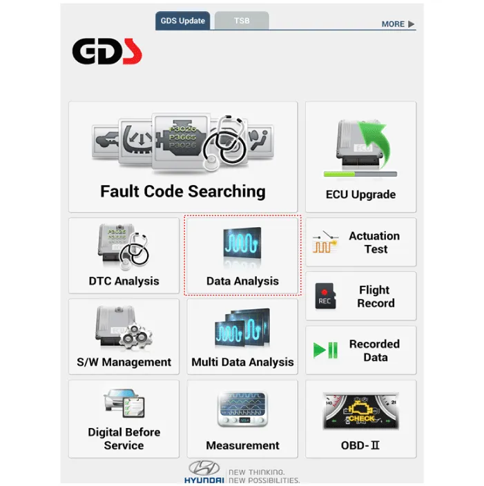
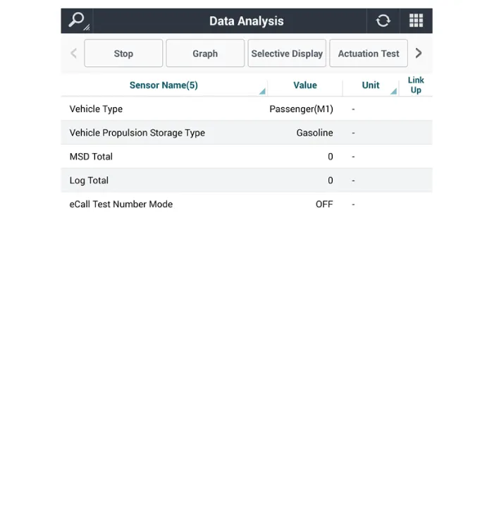
| 3. | Select the 'Current Data' menu to check the current state of the input/output data.
|
eCall System Reset
The eCall System Reset function is to reset when eCall is locked or stopped.
|
| 1. | Turn the ignition switch OFF. |
| 2. | Connect the diagnostic tools. |
| 3. | Turn the ignition switch ON without the engine running. |
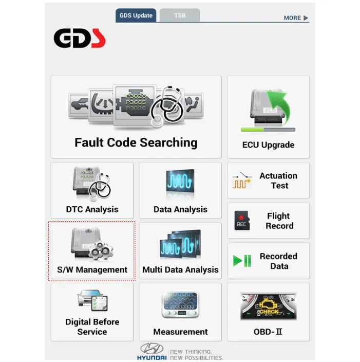
| 4. | Select the "Car Model" and "S/W Management".
|
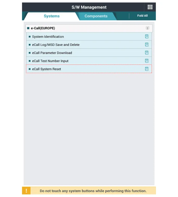
| 5. | Select the "eCall System Reset"
|
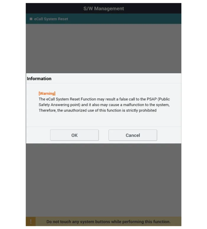
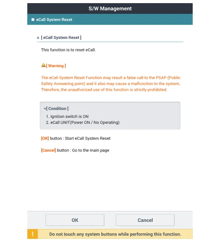
| 6. | Follow the screen instructions to perform the "eCall System Reset".
|
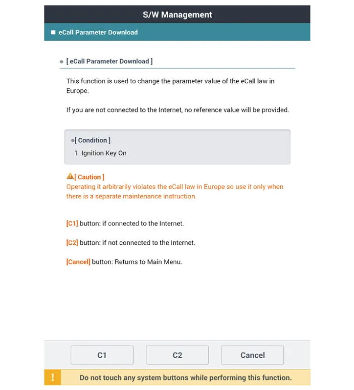
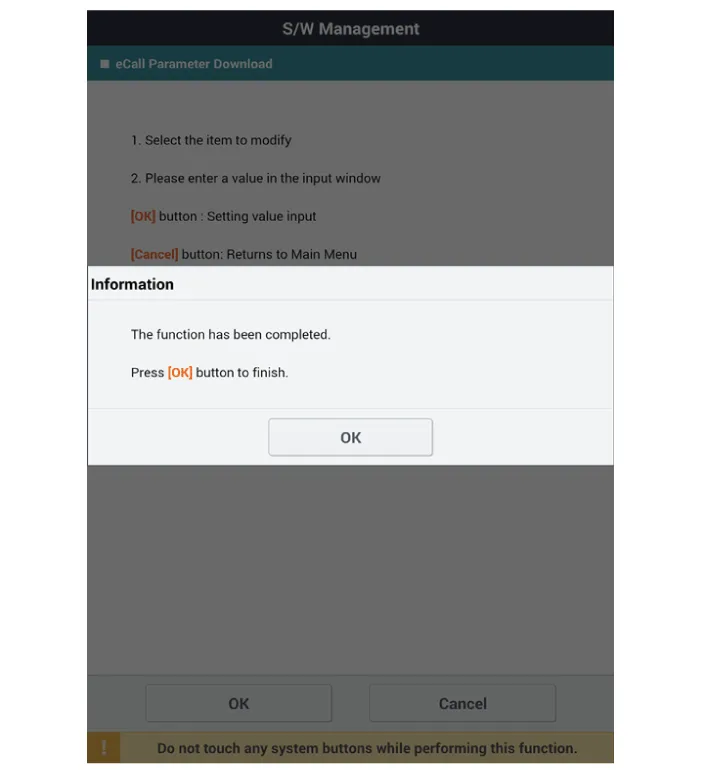
eCall Parameter Download
eCall Parameter Download is used to change the parameter value of the eCall law in Europe.
| 1. | Turn the ignition switch OFF. |
| 2. | Connect the diagnostic tools. |
| 3. | Turn the ignition switch ON without the engine running. |
| 4. | Select the "Car Model" and "S/W Management".
|
| 5. | Select the "eCall Parameter Download"
|

| 6. | Follow the screen instructions to perform the "eCall Parameter Download".
|
SCHEMATIC DIAGRAM
Other information:
Hyundai Ioniq (AE) 2017-2022 Service & Repair Manual: In-car Sensor. Repair procedures
Diagnosis With GDS1.The heating, ventilation and air conditioning can be quickly diagnosed failed parts with vehicle diagnostic system (GDS).※ The diagnostic system (GDS) provides the following information.(1) Self diagnosis : Checking the failure code (DTC) and display.
Hyundai Ioniq (AE) 2017-2022 Service & Repair Manual: Parking Distance Warning (PDW) Sensor. Repair procedures
Removal1.Disconnect the negative (-) battery terminal.2.Remove the front / rear bumper cover.(Refer to Body - "Front Bumper Cover")(Refer to Body - "Rear Bumper Cover")3.Disconnect the connector (A) from the parking assist sensor.4.Remove the sensor (A) by pulling out both ends of the sensor holder.
Categories
- Manuals Home
- Hyundai Ioniq Owners Manual
- Hyundai Ioniq Service Manual
- Engine Clutch System
- What to do in an emergency
- Maintenance
- New on site
- Most important about car

Copyright © 2026 www.hioniqae.com - 0.013