Hyundai Ioniq (AE): Head Lamp Leveling Device / Head Lamp Leveling Switch. Schematic diagrams
Hyundai Ioniq (AE) 2017-2022 Service & Repair Manual / Body Electrical System / Head Lamp Leveling Device / Head Lamp Leveling Switch. Schematic diagrams
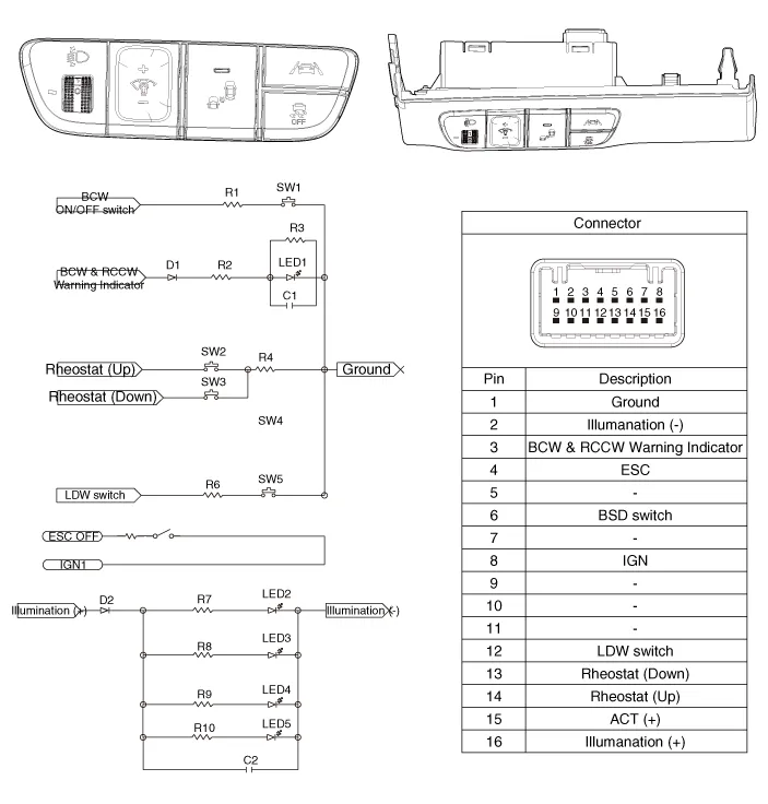
| SCHEMATIC DIAGRAM |
Component Location1. Head lamp leveling actuator2. Head lamp leveling switch
Inspection1.Disconnect the negative (-) battery terminal.2.Remove the crash pad lower panel (A).(Refer to Body - "Crash Pad Lower Panel")3.Disconnect the rheostat switch connector (A).
Other information:
Hyundai Ioniq (AE) 2017-2022 Service & Repair Manual: Intake Actuator. Components and components location
C
Hyundai Ioniq (AE) 2017-2022 Service & Repair Manual: Schematic diagrams
System Block DiagramComponent Parts and Function Outline Component part Function Vehicle-speed sensor, ESP/ABS Control ModuleConverts vehicle speed to pulse.VCUReceives signals from sensor and control switches.
Categories
- Manuals Home
- Hyundai Ioniq Owners Manual
- Hyundai Ioniq Service Manual
- Hybrid Control System
- Engine Control/Fuel System
- Body (Interior and Exterior)
- New on site
- Most important about car

Copyright © 2026 www.hioniqae.com - 0.0169