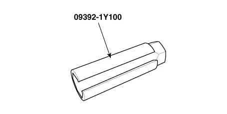
Hyundai Ioniq (AE): Engine Control System / Heated Oxygen Sensor (HO2S). Repair procedures
Hyundai Ioniq (AE) 2017-2022 Service & Repair Manual / Engine Control/Fuel System / Engine Control System / Heated Oxygen Sensor (HO2S). Repair procedures
| Inspection |
| 1. | Turn the ignition switch OFF. |
| 2. | Disconnect the HO2S connector. |
| 3. | Measure resistance between the HO2S terminals 2 and 5 [B1/S1]. |
| 4. | Measure resistance between the HO2S terminals 3 and 4 [B1/S2]. |
| 5. | Check that the resistance is within the specification.
|
| Removal |
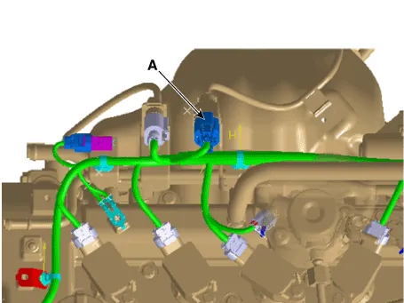
[Bank 1 / Sensor 1]
| 1. | Turn the ignition switch OFF and disconnect the battery negative (-) cable. |
| 2. | Disconnect the connector (A), and then remove the sensor (B).
|


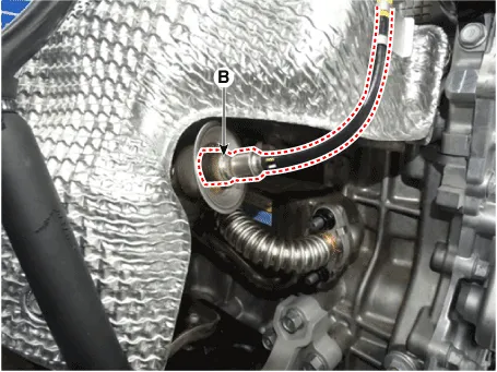
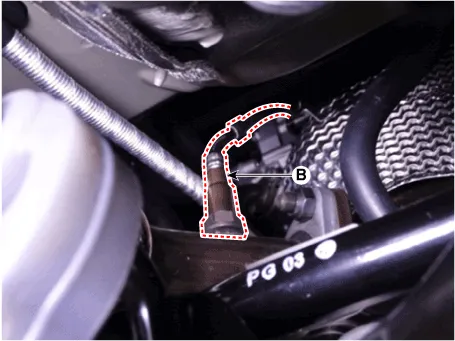
[Bank 1 / Sensor 2]
| 1. | Turn the ignition switch OFF and disconnect the battery negative (-) cable. |
| 2. | Disconnect the connector (A), and then remove the sensor (B).
|
| Installation |
|

|
| 1. | Install in the reverse order of removal.
|
Circuit Diagram
DescriptionInstalled in exhaust manifold, the Exhaust Gas Temperature Sensor (EGTS) #1 for EWGA senses the temperature of exhaust gas flowing into the EWGA.
Other information:
Hyundai Ioniq (AE) 2017-2022 Service & Repair Manual: High voltage shut-off procedures
High Voltage Shut-off Procedures • Be sure to read and follow the "General Safety Information and Caution" before doing any work related with the high voltage system. Failure to follow the safety instructions may result in serious electrical injuries.
Hyundai Ioniq (AE) 2017-2022 Service & Repair Manual: Components and components location
C
Categories
- Manuals Home
- Hyundai Ioniq Owners Manual
- Hyundai Ioniq Service Manual
- Repair procedures
- Theft-alarm System
- Engine Mechanical System
- New on site
- Most important about car

Copyright © 2026 www.hioniqae.com - 0.0164