
Hyundai Ioniq (AE): Seat Electrical / Lumber Support Units. Repair procedures
Hyundai Ioniq (AE) 2017-2022 Service & Repair Manual / Body Electrical System / Seat Electrical / Lumber Support Units. Repair procedures
| Removal |
| 1. | Disconnect the negative (-) battery terminal. |
| 2. | Remove the front seat assembly. (Refer to Body - "Front Seat Assembly") |
| 3. | Remove the seat back. (Refer to Body - "Front Seat Back Cover") |
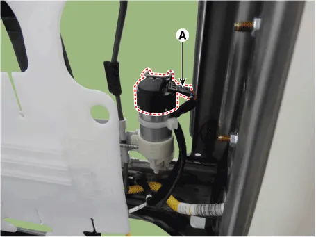
| 4. | Disconnect the lumber support motor connector (A).
|
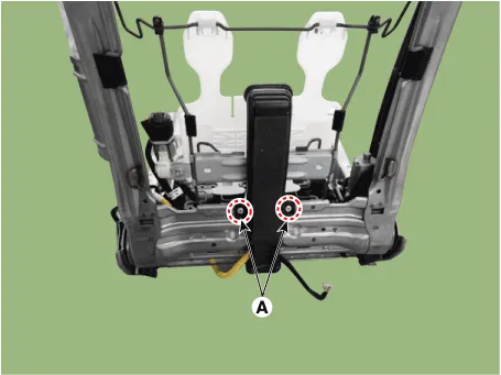
| 5. | Separate the retaining clips (A) from the seat frame.
|
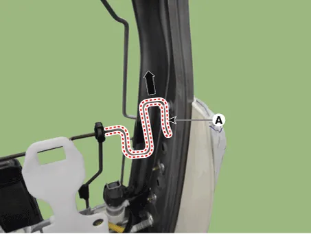
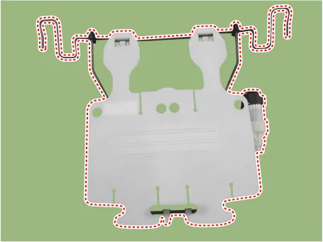
| 6. | Remove the lumber support assembly after disengaging mounting clip (A).
|
| Installation |
| 1. | Install the lumbar support assembly. |
| 2. | Install the seat back cover. |
| 3. | Install the front seat assembly.
|

| Inspection |
Lumbar Support Motor
| 1. | Disconnect the connectors for each motor. [Lumbar Support Motor]
|
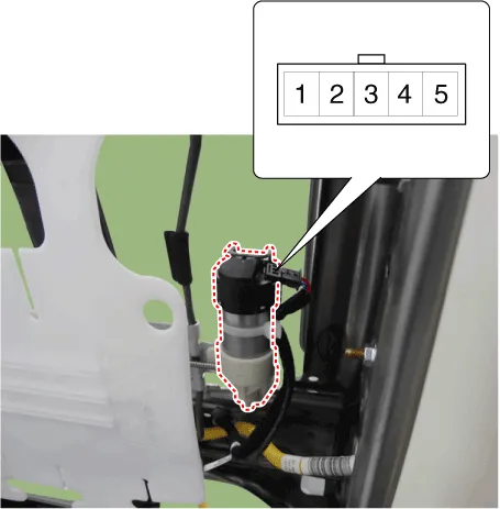
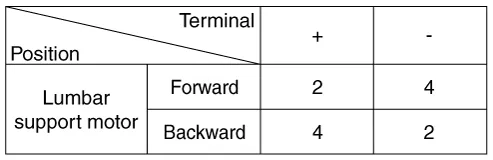
| 2. | With the battery connected directly to the motor terminals, check if the motors run smoothly. |
| 3. | Reverse the connections and check that the motor turns in reverse. |
| 4. | If there is an abnormality, replace the motors.
|
Removal[Ventilation Blower]1.Disconnect the negative (-) battery terminal.2.Remove the front seat.(Refer to Body - "Front Seat Assembly") 3.Remove the blower duct.
Other information:
Hyundai Ioniq (AE) 2017-2022 Service & Repair Manual: Specifications
S
Hyundai Ioniq (AE) 2017-2022 Service & Repair Manual: Schematic diagrams
System Block DiagramComponent Parts and Function Outline Component part Function Vehicle-speed sensor, ESP/ABS Control ModuleConverts vehicle speed to pulse.VCUReceives signals from sensor and control switches.
Categories
- Manuals Home
- Hyundai Ioniq Owners Manual
- Hyundai Ioniq Service Manual
- General Information
- Transmission Gear Oil. Repair procedures
- Components and components location
- New on site
- Most important about car

Copyright © 2026 www.hioniqae.com - 0.0141