Hyundai Ioniq (AE): Engine Control System / Mass Air Flow Sensor (MAFS). Repair procedures
| Inspection |
| 1. | Check the MAFS visually.
|
| 2. | Check any leakage on intake system and intercooler system. |
| Removal |
| 1. | Turn the ignition switch OFF and disconnect the battery (-) cable. |
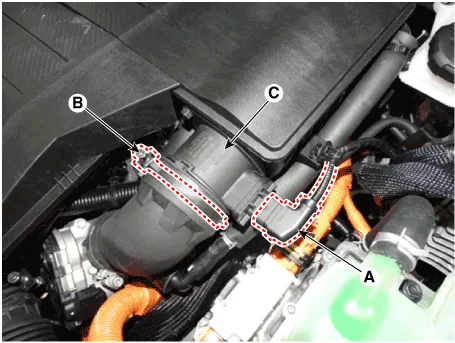
| 2. | Disconnect the mass air flow sensor connector (A) and the installation clamp (B). |
| 3. | Remove the mass air flow sensor (C).
|
| Installation |
|

|
| 1. | Install in the reverse order of removal.
|
Circuit Diagram
DescriptionIntake Air Temperature Sensor (IATS) is included inside Manifold Absolute Pressure Sensor and detects the intake air temperature.To calculate precise air quantity, correction of the air temperature is needed because air density varies according to the temperature.
Other information:
Hyundai Ioniq (AE) 2017-2022 Service & Repair Manual: Blower Unit. Repair procedures
Replacement When prying with a flat-tip screwdriver or use a prying trim tool, wrap it with protective tape, and apply protective tape around the related parts, to prevent damage.1.Disconnect the negative (-) battery terminal.2.Recover the refrigerant with a recovery / recycling / charging station.
Hyundai Ioniq (AE) 2017-2022 Service & Repair Manual: Rear Corner Radar Unit. Repair procedures
Removal1.Disconnect the negative (-) battery terminal.2.Remove the rear bumper.(Refer to Body - "Rear Bumper")3.Remove the rear corner radar unit (A) after loosening the mounting nuts. • Take care not to separate the bracket from rear bumper when removing the rear corner radar sensor.
Categories
- Manuals Home
- Hyundai Ioniq Owners Manual
- Hyundai Ioniq Service Manual
- Heating, Ventilation and Air Conditioning
- Engine Clutch System
- Jump starting procedure
- New on site
- Most important about car
