Hyundai Ioniq (AE): IMS(Integrated Memory System) / Memory power seat unit. Schematic diagrams
| Circuit Diagram |
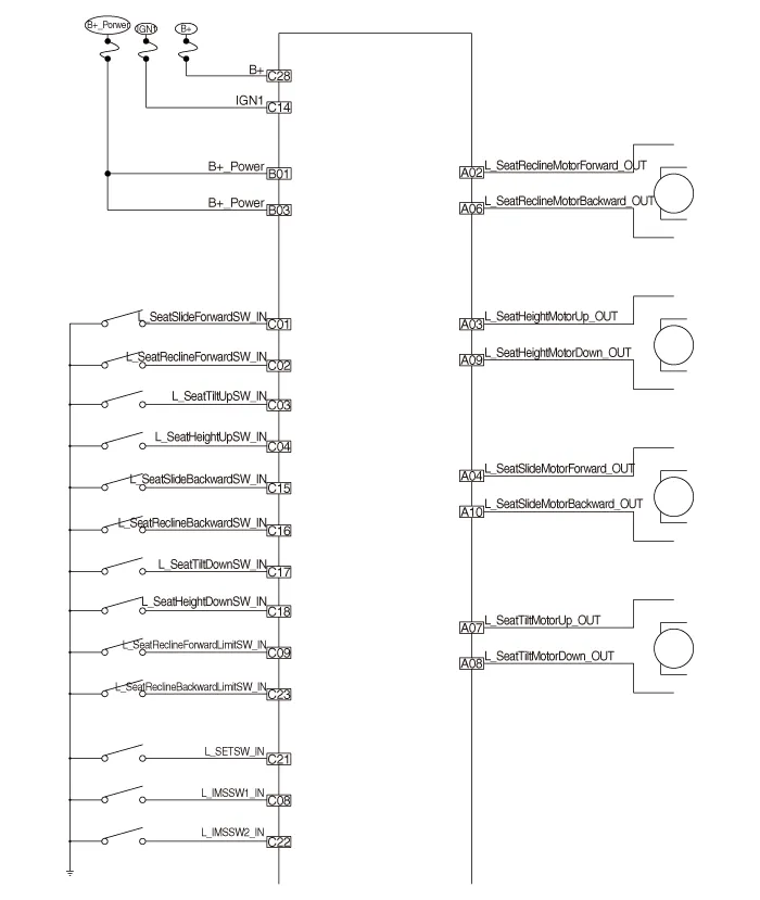

Components No Connecter A Connecter B Connecter C 1-Battery (+)Slide switch signal (Forward)2Reclining motor (Forward)GNDReclining switch signal (Forward)3Height motor (Up)Battery (+)Front tilt switch signal (Up)4Slide motor (Forward)-Reclining switch signal (Forward)5-GND-6Reclining motor (Backward) B-CAN (High)7Tilt motor (Up)B-CAN (Low)8Tilt motor (Down)IMS Switch 19Height motor (Down)Recline limit switch (Forward)10Slide motor (Backward)Slide sensor input11 Tilt sensor input12-13Position sensor (Power)14IGN 115Slide switch (Backward)16Recline switch (Backward)17Tilt switch (Down)18Height switch (Down)19-20Ground21 SET Switch22IMS Switch 223Recline limit switch (Backward)24Seat recline sensor25Seat height sensor (input)26-27-28Battery (+)
Removal1.Disconnect the negative (-) battery terminal.2.Remove the driver seat assembly.(Refer to Body - "Front Seat Assembly")3.Loosening the IMS unit mounting screws.
Other information:
Hyundai Ioniq (AE) 2017-2022 Service & Repair Manual: Photo Sensor. Repair procedures
Inspection1.Turn the ignition switch ON.2.Connect the GDS.3.Emit intensive light toward the photo sensor using a lamp, and check the output voltage change.4.The voltage will rise with higher intensive light and reduce with lower intensive light.1. Auto light signal2.
Hyundai Ioniq (AE) 2017-2022 Service & Repair Manual: Front View Camera Unit. Repair procedures
Removal1.Disconnect the negative (-) battery terminal.2.Remove the front view camera cover (A).3.Disconnect the front view camera connector (A).4.Remove the front view camera after disengaging the mounting bracket (A).Installation1.Align front view camera with windshield bracket using forward edge point (A).
Categories
- Manuals Home
- Hyundai Ioniq Owners Manual
- Hyundai Ioniq Service Manual
- Brake System
- If the 12 Volt Battery is Discharged (Hybrid Vehicle)
- Troubleshooting
- New on site
- Most important about car
