Hyundai Ioniq (AE): Manual Heating and Air Conditioning / Mode selection
The mode selection button controls the direction of the air flow through the ventilation system.
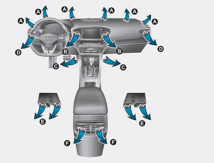
The air flow outlet direction is cycled as follows:
â– MODE DOWN ( )
)

â– MODE UP ( )
)

Face-Level (B, D, F)

Air flow is directed toward the upper body and face. Additionally, each outlet can be controlled to direct the air discharged from the outlet.
Bi-Level (B, C, D, E, F)

Air flow is directed towards the face and the floor.
Floor & Defrost (A, C, E, F)

Most of the air flow is directed to the floor and the windshield with a small amount directed to the side window defrosters.
Floor-Level (A, C, E, F)

Most of the air flow is directed to the floor, with a small amount of the air being directed to the windshield and side window defrosters.
Defrost-Level (A)
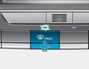
Most of the air flow is directed to the windshield with a small amount of air directed to the side window defrosters.
Interior panel vents
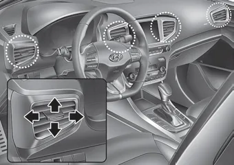
â– Front
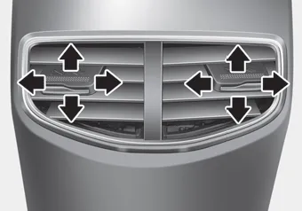
â– Rear
The outlet vents can be opened or closed ( )
using the vent control lever.
)
using the vent control lever.
Also, you can adjust the direction of air delivered from these vents using the vent control lever as shown.
The heating and cooling system can be controlled manually by pushing buttons other than the AUTO button. In this case, the system works sequentially according to the order of buttons selected.
Turn the knob to the right to increase the temperature. Turn the knob to the left to decrease temperature. The temperature will increase or decrease by 1°F/0.
Other information:
Hyundai Ioniq (AE) 2017-2022 Service & Repair Manual: emperature Control Actuator. Components and components location
C
Hyundai Ioniq (AE) 2017-2022 Service & Repair Manual: Blower Unit. Repair procedures
Replacement When prying with a flat-tip screwdriver or use a prying trim tool, wrap it with protective tape, and apply protective tape around the related parts, to prevent damage.1.Disconnect the negative (-) battery terminal.2.Recover the refrigerant with a recovery / recycling / charging station.
Categories
- Manuals Home
- Hyundai Ioniq Owners Manual
- Hyundai Ioniq Service Manual
- Transmission Gear Oil. Repair procedures
- Theft-alarm System
- Maintenance
- New on site
- Most important about car
