Hyundai Ioniq (AE): Hybrid Motor Control System / Motor Control Unit(MCU). Repair procedures
| Removal |
|

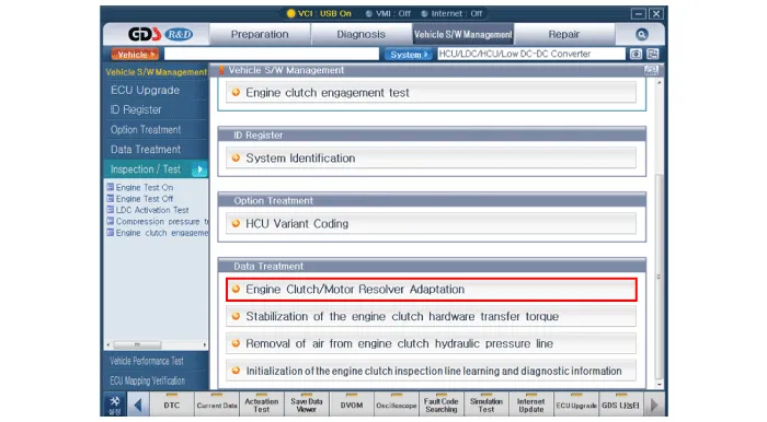
Diagram System CircuitA high-capacity power module is applied to the two high-voltage motors.The power module consists of a high - speed switching circuit that is isolated from the IGBT and DIODE circuits.
DescriptionŌĆó To efficiently control the drive motor, you need to know the absolute location of a motor rotor (permanent magnet).ŌĆó Resolver detects the absolute location of the motor rotor.
Other information:
Hyundai Ioniq (AE) 2017-2022 Service & Repair Manual: Auto Defogging Sensor. Repair procedures
Diagnosis With GDS1.The heating, ventilation and air conditioning can be quickly diagnosed failed parts with vehicle diagnostic system (GDS).ŌĆ╗ The diagnostic system (GDS) provides the following information.(1) Self diagnosis : Checking the failure code (DTC) and display.
Hyundai Ioniq (AE) 2017-2022 Service & Repair Manual: Evaporator Core. Repair procedures
Replacement1.Disconnect the negative (-) battery terminal. 2.Remove the heater and blower assembly.(Refer to Heater - "Heater Unit") 3.Remove the evaporator core cover (A) after loosening the mounting screws.4.Pull out the evaporator temperature sensor (A) from the evaporator core.
Categories
- Manuals Home
- Hyundai Ioniq Owners Manual
- Hyundai Ioniq Service Manual
- Hybrid Control System
- Brake System
- Engine Clutch System
- New on site
- Most important about car
