Hyundai Ioniq (AE): High Voltage Battery Control System / Pre-Charge Resistor. Repair procedures
| Removal |
| 1. | Shut off the high voltage. (Refer to Hybrid Control System - "High Voltage Shut-off Procedures") |
| 2. | Remove the rear seat cushion. (Refer to Body - "Rear Seat Assembly") |
| 3. | Remove the rear door scuff trim. (Refer to Body - "Door Scuff Trim") |
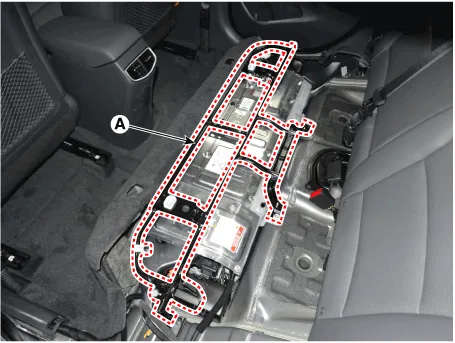
| 4. | Remove the upper frame (A) after loosening the mounting bolts and nuts.
|
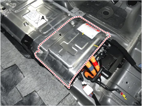
| 5. | Remove the high voltage battery rear cover (A) after loosening the mounting bolts and nuts.
|
| 6. | Remove the inlet cooling duct. (Refer to Hybrid Control System - "Cooling Duct") |
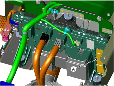
| 7. | Disconnect the pre-charge resistor (A).
|
| Installation |
|

| 1. | Install in the reverse order of removal.
|
| Inspection |
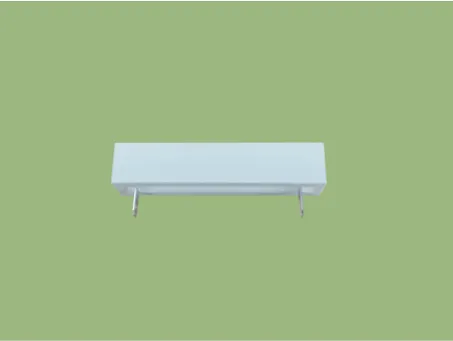
| 1. | Remove the pre-charge resistor. (Refer to High Voltage Battery Control System - "Pre-Charge Resistor") |
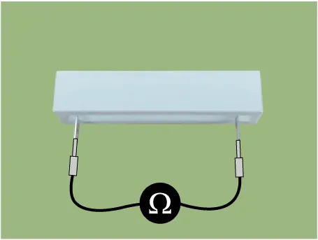
| 2. | Check for continuity between the terminals using an ohmmeter.
|
Circuit Diagram
DescriptionBattery Current Sensor is integrated into the Power Relay Assembly (PRA) and measures the current of the high voltage battery during charging or discharging.
Other information:
Hyundai Ioniq (AE) 2017-2022 Service & Repair Manual: General safety information and caution
General Safety Information and CautionBe careful of the following precautions when driving the vehicle using the smart cruise control system. • The smart cruise control system may have limits in detecting distance to the vehicle ahead due to road and traffic conditions.
Hyundai Ioniq (AE) 2017-2022 Service & Repair Manual: Repair procedures
Diagnosis with GDS1.REAR CORENER RADAR system defects can be quickly diagnosed with the GDS. GDS operates actuator quickly to monitor, input/output value and self diagnosis.2.Connect the cable of GDS to the data link connector in driver side crash pad lower panel, turn the power on GDS.
Categories
- Manuals Home
- Hyundai Ioniq Owners Manual
- Hyundai Ioniq Service Manual
- Maintenance
- Engine Control/Fuel System
- Front Disc Brake. Repair procedures
- New on site
- Most important about car
