Hyundai Ioniq (AE): Fuses And Relays / Relay Box (Engine Compartment). Components and components location
Hyundai Ioniq (AE) 2017-2022 Service & Repair Manual / Body Electrical System / Fuses And Relays / Relay Box (Engine Compartment). Components and components location
| Component Location |
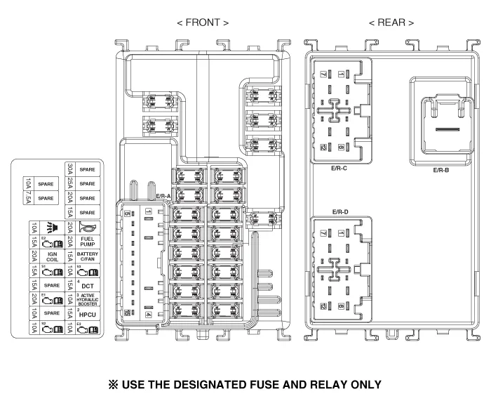
Engine Room Junction Block
| E/R Junction Block |
| Circuit (E/R Junction Block) |

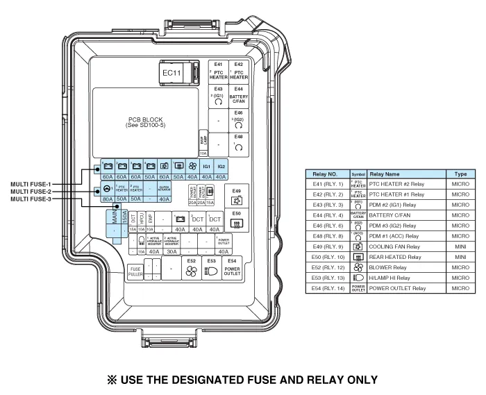
Metal Core Block (PCB)
| PCB Block |
| Circuit (PCB Block) |

Component Location[Engine Room]1. Engine room junction block[Interior Relay]1. Smart junction block (SJB)2. ICM relay block
Inspection1.Disconnect the negative (-) battery terminal.2.Pull out the relay from the engine compartment relay block.Power Relay (Type A) Check for continuity between the terminals.
Other information:
Hyundai Ioniq (AE) 2017-2022 Service & Repair Manual: Duct Sensor. Components and components location
C
Hyundai Ioniq (AE) 2017-2022 Service & Repair Manual: Special service tools
Special Service Tools Tool Name / Number Illustration Description LKA Compensator(09964-C1100)Used for compensating front view camera unitBCW Sensor Correction Tool Set(09958-3T500)Used to correct the blind-spot radar unit.
Categories
- Manuals Home
- Hyundai Ioniq Owners Manual
- Hyundai Ioniq Service Manual
- Hybrid Vehicle Engine Compartment
- Troubleshooting
- Transmission Gear Oil. Repair procedures
- New on site
- Most important about car

Copyright © 2026 www.hioniqae.com - 0.0138