Hyundai Ioniq (AE): Multifunction Switch / Repair procedures
Hyundai Ioniq (AE) 2017-2022 Service & Repair Manual / Body Electrical System / Multifunction Switch / Repair procedures
| Removal |
| 1. | Disconnect the negative (-) battery terminal. |
| 2. | Remove the steering wheel. (Refer to Steering System - "Steering Wheel") |
| 3. | Remove the steering column upper and lower shrouds after loosening the screws. (Refer to Body - "Steering Column Shroud Panal") |
| 4. | Remove the clock spring. (Refer to Restraint - "Driver Airbag (DAB) Module and Clock Spring") |
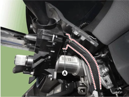
| 5. | Disconnect the multifunction switch connector (A).
|
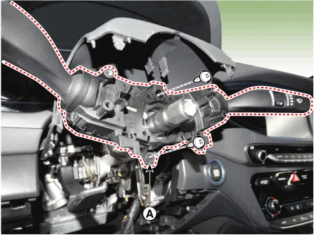
| 6. | Remove the multifunction switch assembly (A) after loosening the screws.
|
| Installation |
| 1. | Install the multifunction switch. |
| 2. | Install the clock spring. |
| 3. | Install the steering column upper and lower shrouds. |
| 4. | Install the steering wheel. |
| 5. | Connect the negative (-) battery terminal. |
| Inspection |
Multifunction Switch Inspection
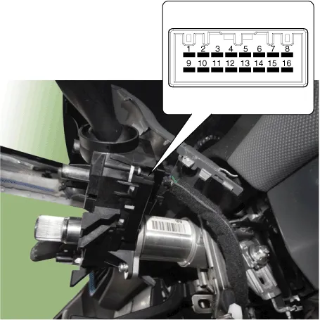
| 1. | Check for continuity between the terminals in each switch position according to the table.
[Left Handle Drive]
[Right Handle Drive]
|
Inspection (with GDS)
| 1. | The body electrocal system can be quickly diagnosed failed parts with vehicle diagnostic system(GDS). The diagnostic system (GDS) provides the following information.
|
| 2. | Select the "Car Model" and the system to be checked in order to check the vehicle with the tester. |
| 3. | Select the "Body Control Module (BCM)" to check the multi function switch. |
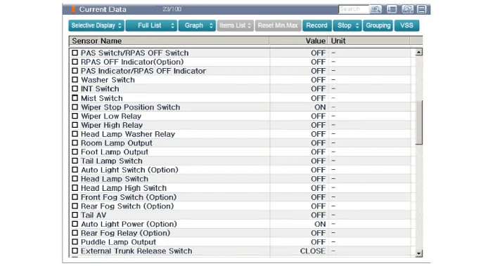
| 4. | Select the "Current Data" menu to search the current state of the input/output data. The input/output data for the sensors corresponding to the multi function switch can be checked.
|
Component1. Steering column2. Multifunction switch3. Screw4. Clock spring
Other information:
Hyundai Ioniq (AE) 2017-2022 Service & Repair Manual: Mode Control Actuator. Description and operation
DescriptionThe mode control actuator is located at the heater unit.It adjusts the position of the mode door by operating the mode control actuator based on the signal of the A/C control unit. Pressing the mode select switch makes the mode control actuator shift in order of Vent → Bi-Level → Floor → Mix.
Hyundai Ioniq (AE) 2017-2022 Service & Repair Manual: Description and operation
DescriptionRear view monitor (RVM) will activate when the backup light is ON with the ignition switch ON and the shift lever in the R position.This system is a supplemental system that shows behind the vehicle through the AV monitor while backing-up. • This system is a supplementary function only.
Categories
- Manuals Home
- Hyundai Ioniq Owners Manual
- Hyundai Ioniq Service Manual
- Heating, Ventilation and Air Conditioning
- Jump starting procedure
- What to do in an emergency
- New on site
- Most important about car

Copyright © 2026 www.hioniqae.com - 0.0179