Hyundai Ioniq (AE): Manifold Absolute Pressure Sensor (MAPS) / Repair procedures
| Inspection |
| 1. | Connect the GDS on the Data Link Connector (DLC). |
| 2. | Measure the output voltage of the MAPS at idle and IG ON.
|
| Removal |
| 1. | Turn ignition switch OFF and disconnect the negative (-) battery cable. |
| 2. | Remove the air cleaner assembly (Refer to Engine Mechanical System - "Air Cleaner") |
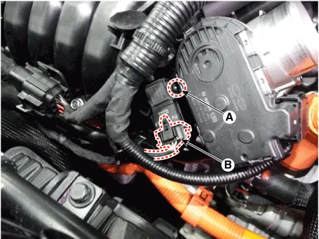
| 3. | Disconnect the manifold absolute pressure sensor connector (A). |
| 4. | Remove the installation bolt (B), and then remove the sensor from the surge tank.
|
| Installation |
|

|
| 1. | Install in the reverse order of removal.
|
Circuit Diagram
DescriptionMAFS uses a hot-film type sensing element to measure the mass of intake air entering the engine, and send the signal to ECM.A large amount of intake air represents acceleration or high load conditions while a small amount of intake air represents deceleration or idle.
Other information:
Hyundai Ioniq (AE) 2017-2022 Service & Repair Manual: Blower Motor. Repair procedures
Inspection1.Connect the battery voltage and check the blower motor rotation.2.If the blower motor does not operate well, substitute with a known-good blower motor and check for proper operation.3.Replace the blower motor if it is proved that there is a problem with it.
Hyundai Ioniq (AE) 2017-2022 Service & Repair Manual: General safety information and caution
General Safety Information and CautionBe careful of the following precautions when driving the vehicle using the smart cruise control system. • The smart cruise control system may have limits in detecting distance to the vehicle ahead due to road and traffic conditions.
Categories
- Manuals Home
- Hyundai Ioniq Owners Manual
- Hyundai Ioniq Service Manual
- Hybrid Vehicle Engine Compartment
- Checking the Coolant Level
- Hybrid Control System
- New on site
- Most important about car
