Hyundai Ioniq (AE): High Voltage Battery Control System / Safety Plug. Repair procedures
| Removal |
| 1. | Turn the ignition switch OFF and disconnect the auxiliary 12V battery negative (-) terminal. |
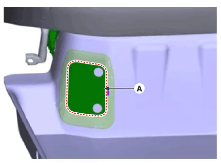
| 2. | Remove the safety plug cover (A).
|
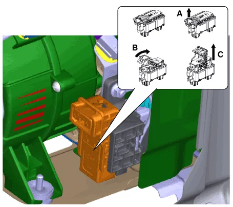
| 3. | Unfasten the hook (A) and then remove the safety plug (C) by pulling the lever (B) to the direction of arrow.
|
| Installation |
|

| 1. | Install the Safety Plug in the reverse order of removal. |
Circuit Diagram
DescriptionThe Power Relay Assembly (PRA) consists of the positive and negative main relays, pre-charge relay, pre-charge resistor and battery current sensor.
Other information:
Hyundai Ioniq (AE) 2017-2022 Service & Repair Manual: Photo Sensor. Description and operation
Description The photo sensor is located at the center of the defrost nozzles.The photo sensor contains a photovoltaic (sensitive to sunlight) diode. The solar radiation received by its light receiving portion, generates an electromotive force in proportion to the amount of radiation received which is transferred to the automatic temperature control
Hyundai Ioniq (AE) 2017-2022 Service & Repair Manual: Blower Unit. Repair procedures
Replacement When prying with a flat-tip screwdriver or use a prying trim tool, wrap it with protective tape, and apply protective tape around the related parts, to prevent damage.1.Disconnect the negative (-) battery terminal.2.Recover the refrigerant with a recovery / recycling / charging station.
Categories
- Manuals Home
- Hyundai Ioniq Owners Manual
- Hyundai Ioniq Service Manual
- Engine Control/Fuel System
- Brake System
- General Information
- New on site
- Most important about car
