Hyundai Ioniq (AE): Autonomous Emergency Braking(AEB) System / Schematic diagrams
| Schematic Diagram |
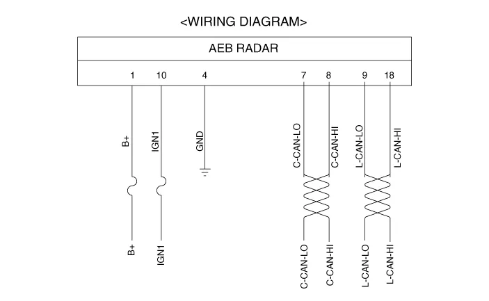
| Terminal Function |

|
No
|
Terminal function
|
| 1 | B+ |
| 2 | NC |
| 3 | NC |
| 4 | GND |
| 5 | NC |
| 6 | NC |
| 7 | C-CAN_Low |
| 8 | C-CAN_High |
| 9 | L-CAN_Low |
| 10 | IGN1 |
| 11 | NC |
| 12 | NC |
| 13 | NC |
| 14 | NC |
| 15 | NC |
| 16 | NC |
| 17 | NC |
| 18 | L-CAN_High |
ComponentsThe following is the configuration of the AEB system.– Detection device (radar and camera) that can recognize potential obstacles in the front.
InspectionAEB function ON / OFF switch was included to USM (User Setting Menu) and the state of the factory is ON.When the IGN On, maintain ON condition by default.
Other information:
Hyundai Ioniq (AE) 2017-2022 Service & Repair Manual: emperature Control Actuator. Description and operation
DescriptionThe temperature control actuator is located at the heater unit. It regulates the temperature by the procedure as follows. The signal from the control unit adjusts the position of the temperature door by operating the temperature switch. Then the temperature will be regulated by the hot/cold air ratio decided by the position of the temper
Hyundai Ioniq (AE) 2017-2022 Service & Repair Manual: Parking Distance Warning (PDW) Sensor. Repair procedures
Removal1.Disconnect the negative (-) battery terminal.2.Remove the front / rear bumper cover.(Refer to Body - "Front Bumper Cover")(Refer to Body - "Rear Bumper Cover")3.Disconnect the connector (A) from the parking assist sensor.4.Remove the sensor (A) by pulling out both ends of the sensor holder.
Categories
- Manuals Home
- Hyundai Ioniq Owners Manual
- Hyundai Ioniq Service Manual
- Brake System
- Hybrid Control System
- General Information
- New on site
- Most important about car
