Hyundai Ioniq (AE): Dual Clutch Transmission Control System / Shift Cable. Repair procedures
Hyundai Ioniq (AE) 2017-2022 Service & Repair Manual / DCT(Dual Clutch Transmission) System / Dual Clutch Transmission Control System / Shift Cable. Repair procedures
| Removal |
|

|

| 1. | Shut off the High Voltage circuit. (Refer to General Information - "High Voltage Shutoff Procedure") |
| 2. | Remove the engine room under cover. (Refer to Engine And Transaxle Assembly - "Engine Room Under Cover") |
| 3. | Loosen the drain plug, and drain the inverter coolant. Remove the reservoir cap to help drain the coolant faster. (Refer to Hybrid Motor System - "Coolant") |
| 4. | Remove the HPCU (Hybrid Power Control Unit). (Refer to Hybrid Control System - "Hybrid Power Control Unit (HPCU)") |
| 5. | Remove the ECM (Engine Control Module) and TCM (Transmssion Control Module). (Refer to Engine Control/Fuel System - "Engine Control Module (ECM)") (Refer to Dual Clutch Control System - "DCT Control Module (TCM)") |
| 6. | Remove the HPCU (Hybrid Power Control Unit) tray. (Refer to Hybrid Control System - "Hybrid Power Control Unit (HPCU)") |
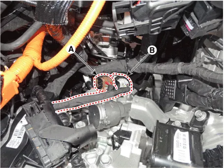
| 7. | Disconnect the gear actuator motor connector (A) and solenoid connector (B).
|
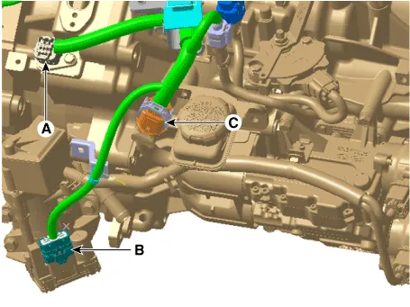
| 8. | Disconnect the hybrid motor connector (A) and engine clutch actuator connector (B). |
| 9. | Disconnect the DCT clutch actuator connector (C).
|
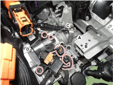
| 10. | Disconnect the inhibitor switch connector (A) and input shaft speed sensor connector (B). |
| 11. | Remove the ground bolt (C) and wiring bracket bolt (D).
|
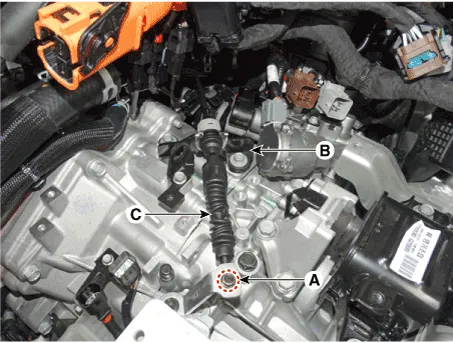
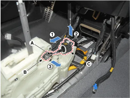
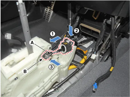
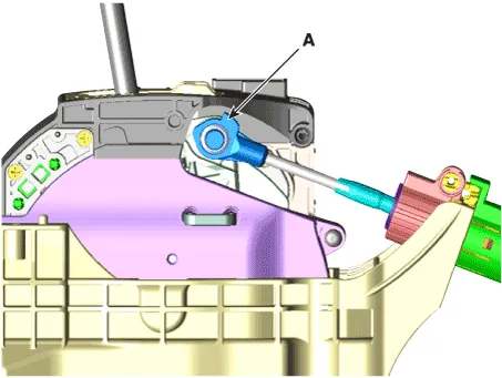
| 12. | Remove the shift cable (C) from the cable bracket (B), after loosening the mounting nut (A).
|
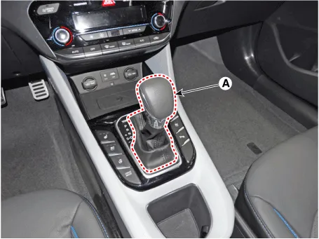
| 13. | Remove the shift lever knob & boots (A) pull both of it up.
|
| 14. | Remove the floor console assembly. (Refer to Body - "Floor Console") |
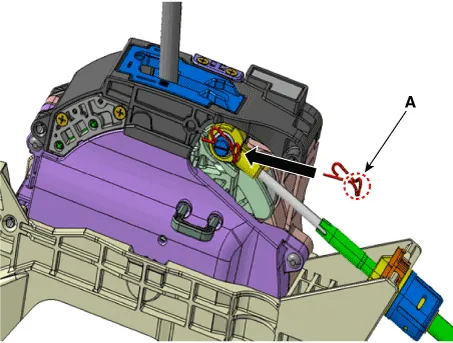
| 15. | Disconnect the shift cable.
|
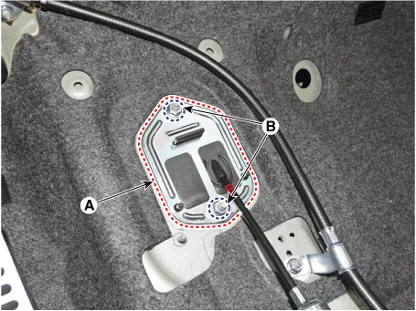
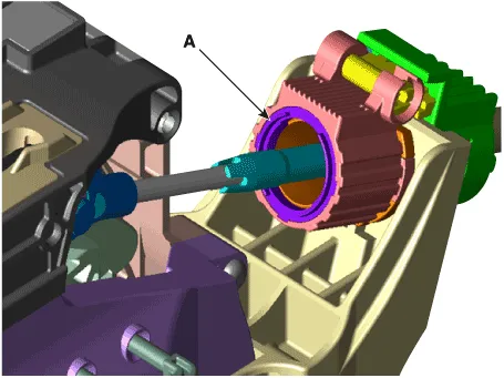
| 16. | Remove the retainer (A) by loosening the nuts (B-2ea).
|
| 17. | Remove the shift cable from the vehicle. |
| Installation |
| 1. | Install the retainer (A) and then tighten the nut (B-2ea).
|
| 2. | Install the shift cable (B) and then fix the snap pin (A).
|

| 3. | Install the shift cable (A) in the cable bracket (B). |
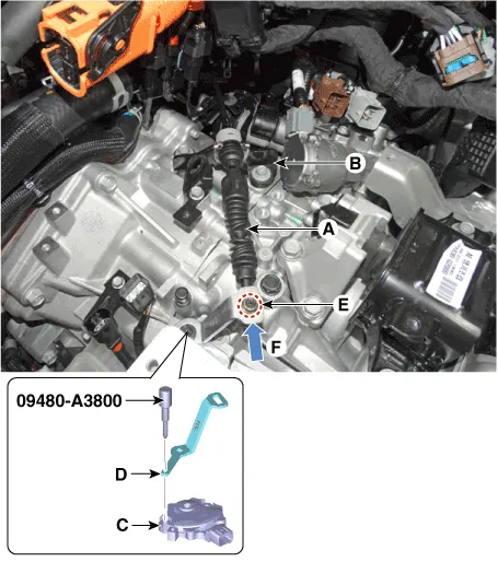
| 4. | Align the hole (C) in the manual control lever with the "N" position hole (D) of the inhibitor switch and then insert the inhibitor switch guide pin (SST No. : 09480-A3800). |
| 5. | Lightly tighten the nut (E) after connected the shift cable (B) in the manual control lever. |
| 6. | Tighten the nut (E) after Push shift cable (B) lightly to "F" direction shown to eliminate free play of shift cable.
|
| 7. | Remove the inhibitor switch guide pin (SST No. : 09480-A3800) from the hole. |
| 8. | Install the engine room under cover. (Refer to Engine Mechanical System - "Engine Room Under Cover") |
| 9. | Install the HPCU (Hybrid Power Control Unit) tray. (Hybrid Control System - "HPCU") |
| 10. | Install the ECM (Engine Controm Module) and TCM (Transmission Control Module) (Refer to Engine Control/Fuel System - "ECM") (Refer to Dual Clutch Control System - "TCM") |
| 11. | Install the HPCU (Hybrid Power Control Unit). (Hybrid Control System - "HPCU") |
| 12. | Bleed air from the hybrid motor cooling system using the GDS. (Refer to Hybrid Motor System- "Coolant") |
| 13. | Install the floor console assembly. (Refer to Body - "Floor Console")
|
Components1. Shift lever knob & boots assembly2. Shift lever assembly3. Shift cable4. Manual control lever5. Shift cable retainer
Categories
- Manuals Home
- Hyundai Ioniq Owners Manual
- Hyundai Ioniq Service Manual
- Washer Fluid
- Hybrid Control System
- If the 12 Volt Battery is Discharged (Hybrid Vehicle)
- New on site
- Most important about car

Copyright © 2026 www.hioniqae.com - 0.0159