Hyundai Ioniq (AE): ETC (Electronic Throttle Control) System / Specifications
| Specification |
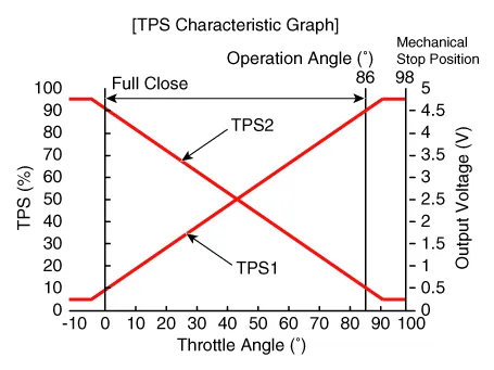
[Throttle Position Sensor (TPS)]
|
Throttle angle (°)
|
Output Voltage (V) [Vref=5V]
| |
|
TPS1
|
TPS2
| |
| 0 | 0.5 | 4.5 |
| 10 | 0.96 | 4.05 |
| 20 | 1.41 | 3.59 |
| 30 | 1.87 | 3.14 |
| 40 | 2.32 | 2.68 |
| 50 | 2.78 | 2.23 |
| 60 | 3.23 | 1.77 |
| 70 | 3.69 | 1.32 |
| 80 | 4.14 | 0.86 |
| 90 | 4.6 | 0.41 |
| 98 | 4.65 | 0.35 |
| C.T (0) | 0.5 | 4.5 |
| W.O.T (86) | 4.41 | 0.59 |
[ETC Motor]
|
Item
|
Specification
|
| Coil Resistance (Ω) | 0.3 - 100 [20°C (68°F)] |
DescriptionThe Electronic Throttle Control (ETC) System consists of a throttle body with an integrated control motor and throttle position sensor (TPS).
Fail-Safe Mode Item Fail-Safe ETC MotorThrottle valve stuck at 7°TPSTPS 1 faultReplace it with TPS 2TPS 2 faultReplace it with TPS 1TPS 1, 2 faultThrottle Angle (°) Throttle valve stuck at 7°Duty (%)• TPS1 : 13.
Other information:
Hyundai Ioniq (AE) 2017-2022 Service & Repair Manual: Components and components location
C
Hyundai Ioniq (AE) 2017-2022 Service & Repair Manual: Description and operation
DescriptionRear corner radar is a system that uses two magnetic wave radar sensors attached on the rear panel to measure the distance from the following vehicles and provides the sensing and (visual and auditory) alarm of any vehicle coming into the blind spot.
Categories
- Manuals Home
- Hyundai Ioniq Owners Manual
- Hyundai Ioniq Service Manual
- Checking the Coolant Level
- Maintenance
- Suspension System
- New on site
- Most important about car

Copyright © 2026 www.hioniqae.com - 0.0184