Hyundai Ioniq (AE): High Voltage Battery System / Sub Battery Pack Assembly (Sub-BPA). Repair procedures
| Check the target charging voltage when replacing with a new module |
| 1. | Turn OFF the ignition switch. |
| 2. | Connect the diagnostic tool device to the self-diagnosis connector (DLC). |
| 3. | Turn ON the ignition switch. |
| 4. | Check the "Fault Code" in the diagnostic tool fault diagnosis. |
| 5. | When the following fault code is identified, check the faulty module and replace the cell monitoring unit or the corresponding module.
|

| 1. | Turn OFF the ignition switch. |
| 2. | Connect the diagnostic tool device to the self-diagnosis connector (DLC). |
| 3. | Turn ON the ignition switch. |
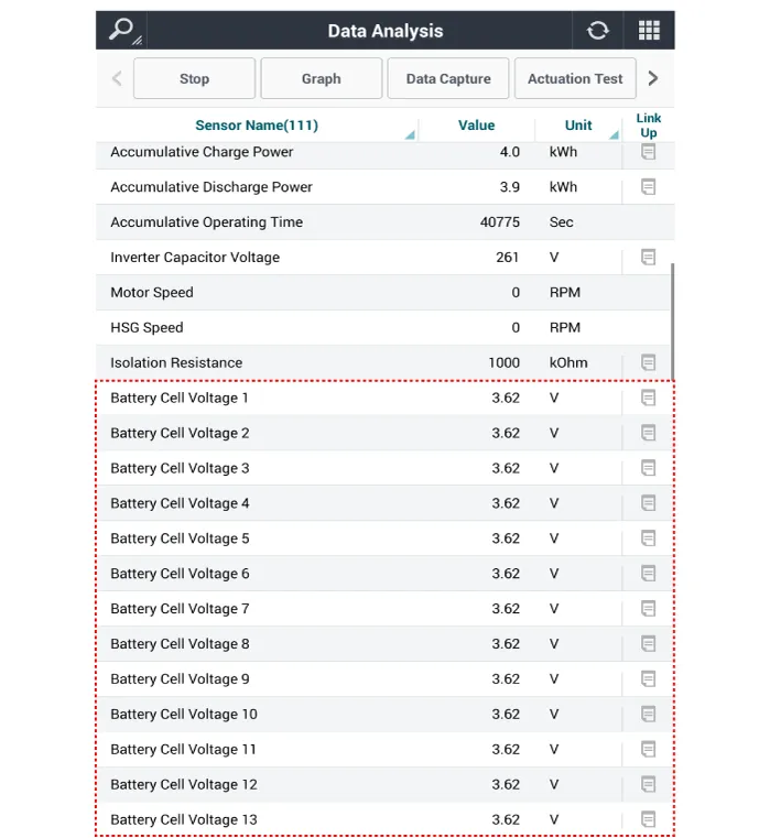
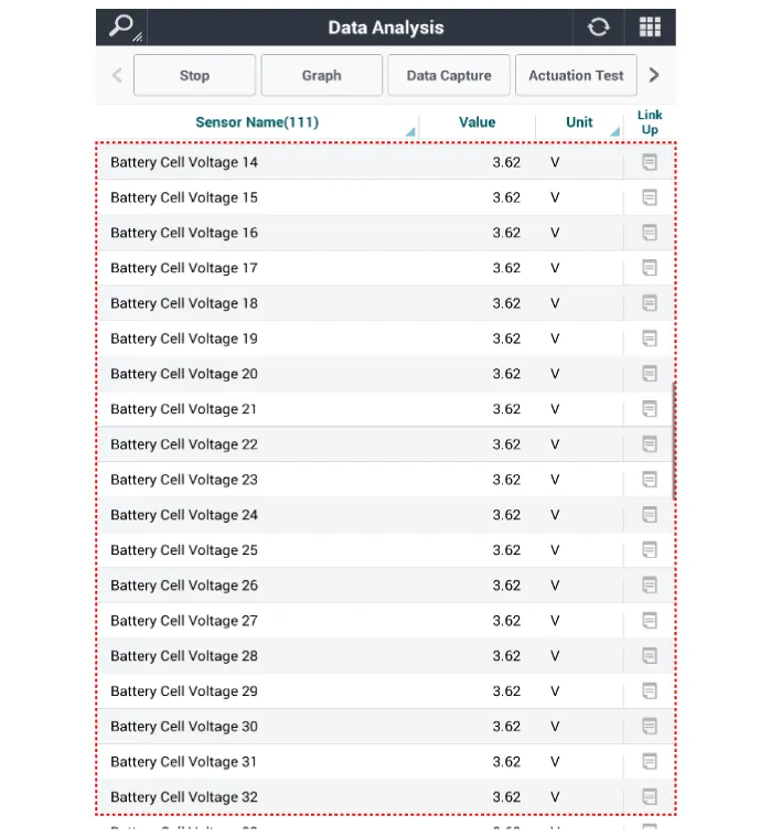
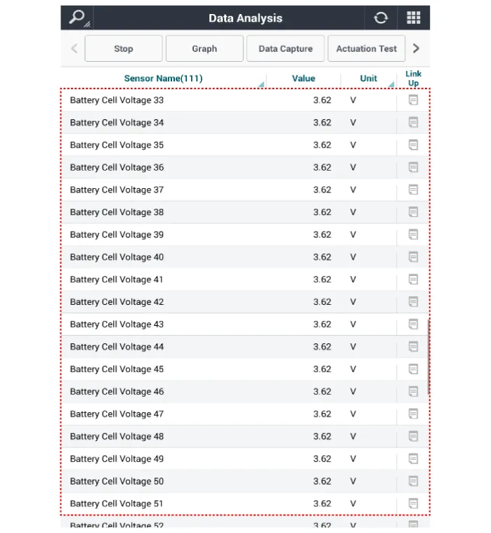
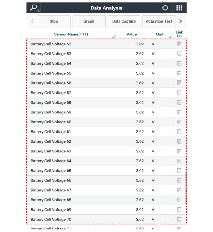
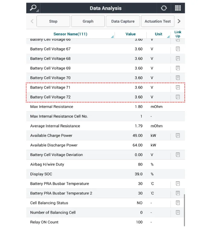
| 4. | Check the maximum and minimum voltages of the cell included in the normal module (excluding the cell numbers identified during the no. 1 process) through the "cell voltage" of diagnostic tool service data.
|
| 5. | Put the maximum voltage and minimum voltage identified during the no. 4 process to the below formula and calculate the target charging voltage when replacing with the new module. |
| 6. | Before installing the new module, charge or discharge the new module to the target voltage using MIDTRONICS (xMB-9640 Module Balancer).
※ It is necessary to calculate the minimum/maximum cell voltage from the cells of the normal modules except the faulty modules.
|
|
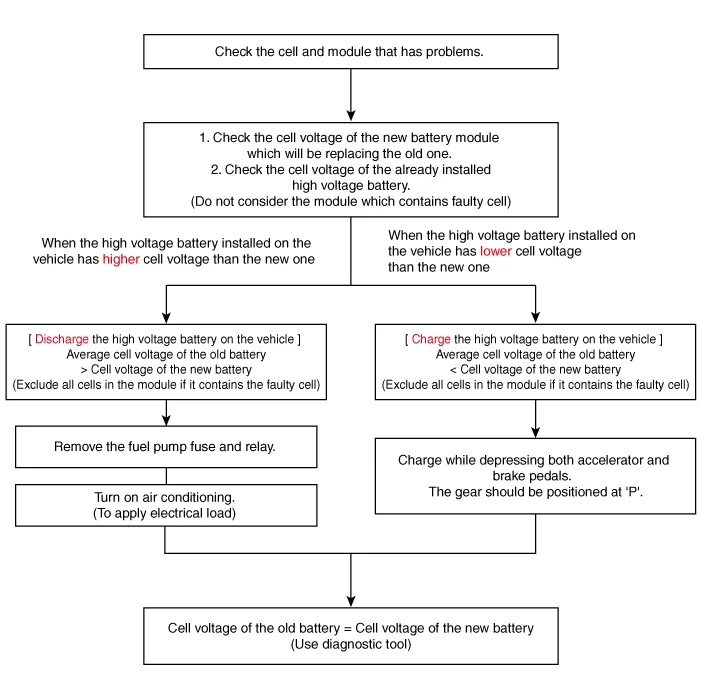
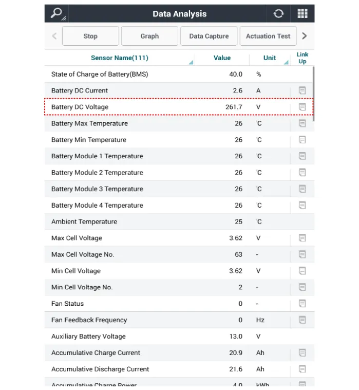
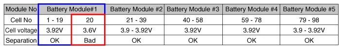
| 1. | Locate the module containing the cell with problem, using diagnostic tool. (Sensor data diagnosis → Battery Management System (BMS) → Battery pack voltage, maximum cell voltage, minimum cell voltage) |
| 2. | Check the voltage of all cells except the module which does not contain the cell with issues. |
| 3. | Check the voltage of the new module. Then calculate the average voltage by dividing the module voltage by the number of the cells.
|
| Discharge |
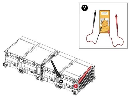
| 1. | Discharge the cell while cheking the voltage using diagnostic tool. (Sensor data diagnosis → Battery Management System (BMS) → Battery pack voltage, maximum cell voltage, minimum cell voltage) |
| 2. | Remove the engine room junction box. |
| 3. | Remove the fuel pump fuse (A).
|

| 4. | Turn on the air conditioning to discharge high voltage battery. (To overload the electrical system) Continue until the voltage of the battery matches the voltage of the new module cell.
|
| Charge |
| 1. | Charge the cell while cheking the voltage using diagnostic tool. (Sensor data diagnosis → Battery Management System (BMS) → Battery pack voltage, maximum cell voltage, minimum cell voltage) |
| 2. | Depress the accelerator and brake pedals at the same time for charging. (To run the engine)
|
| 3. | Simultaneously depressing the both pedals will create the pack voltage approximately -20A. At the moment the voltage reaches the target, immediately release the pedals. It will temporarily drop the pack voltage to 0V, causing voltage dip approximately 40mV. Therefore charge about 40mV more than the target voltage.
|
| Disassembly |
|

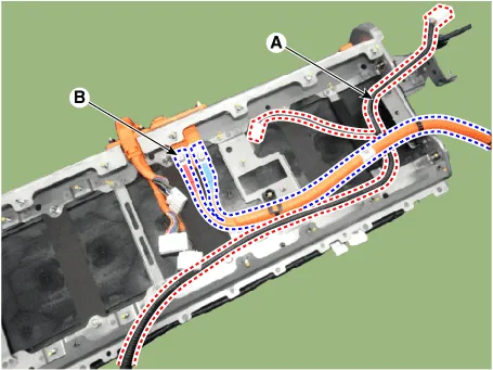
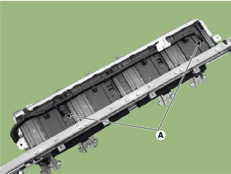
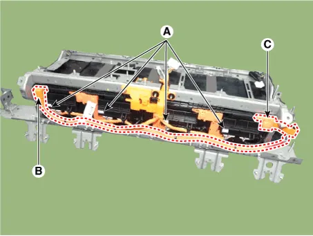
| 1. | Remove the BMS ECU, power relay assembly, cooling fan extension wiring (A). |
| 2. | Remove the installation bolt, then remove the safety plug cable (B).
|
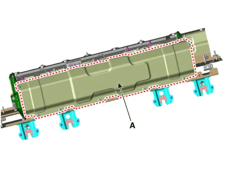
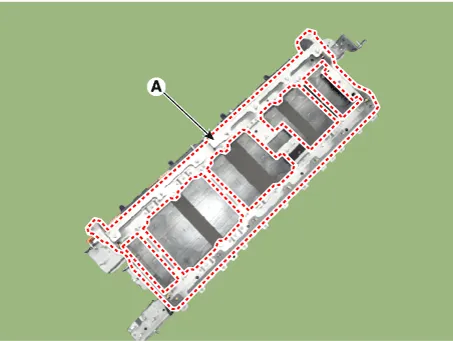
| 3. | Remove the installation nut, then remove the battery pack assembly front cover (A).
|
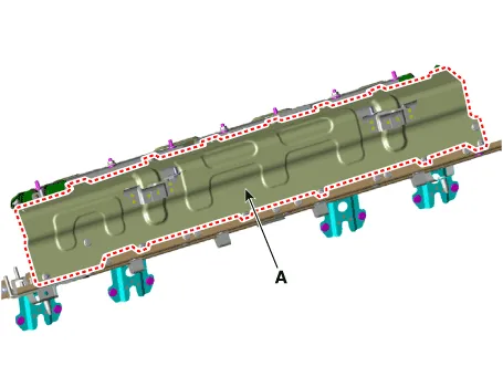
| 4. | Remove the installation nut, then remove the battery pack assembly rear cover (A).
|
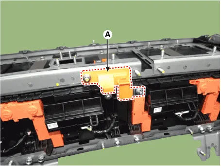
| 5. | Remove the battery temperature sensor (A).
|
| 6. | Remove the installation nut, then remove the battery module connector (A). |
| 7. | Remove the installation nut, then remove the power cable (+) terminal (B) and (-) terminal (C)
|
| 8. | Remove the installation nut, then remove the safety plug bus bar (A).
|
| 9. | Remove the installation bolt, then remove the battery pack bracket (A).
|
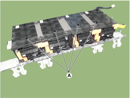
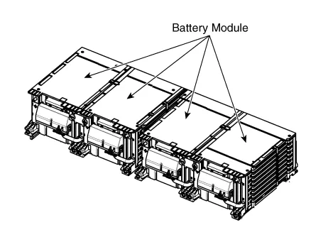
| 10. | Remove the installation bolt, then remove the battery module (A) from the high voltage battery plate.
|
| Reassembly |
|
| 1. | Install the battery pack assembly in the reverse order of removal.
|
Removal • Be sure to read and follow the "General Safety Information and Caution" before doing any work related with the high voltage system.
DescriptionThe Power Relay Assembly (PRA) consists of the positive and negative main relays, pre-charge relay, pre-charge resistor and battery current sensor.
Other information:
Hyundai Ioniq (AE) 2017-2022 Service & Repair Manual: Photo Sensor. Repair procedures
Inspection1.Turn the ignition switch ON.2.Connect the GDS.3.Emit intensive light toward the photo sensor using a lamp, and check the output voltage change.4.The voltage will rise with higher intensive light and reduce with lower intensive light.1. Auto light signal2.
Hyundai Ioniq (AE) 2017-2022 Service & Repair Manual: Description and operation
Cruise ControlThe cruise control system is engaged by the cruise "ON/OFF" main switch located on right of steering wheel column. The system has the capability to cruise, coast, accelerate and resume speed.It also has a safety interrupt, engaged upon depressing brake or shifting select lever.
Categories
- Manuals Home
- Hyundai Ioniq Owners Manual
- Hyundai Ioniq Service Manual
- Transmission Gear Oil. Repair procedures
- General Information
- Brake System
- New on site
- Most important about car
