
Hyundai Ioniq (AE): Sun Roof / Sunroof Switch. Repair procedures
| Inspection |
| 1. | Disconnect the negative (-) battery terminal. |
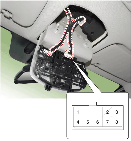
| 2. | Open the sunglass case cover from the overhead console and remove the 2 screws holding the overhead console. Disconnect the switch connector and Map lamp connector, and then remove the overhead console lamp (A).
|
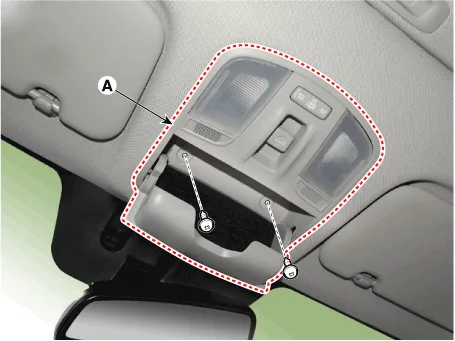
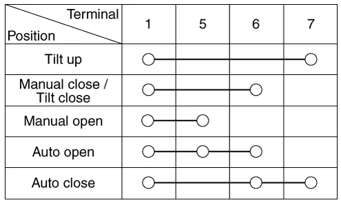
| 3. | Check for continuity between the terminals.
|
Circuit Diagram
Inspection 1.Disconnect the negative (-) battery terminal.2.Remove the roof trim.(Refer to Body - "Roof Trim")3.Disconnect the sunroof motor (A) connector.
Other information:
Hyundai Ioniq (AE) 2017-2022 Service & Repair Manual: Mode Control Actuator. Description and operation
DescriptionThe mode control actuator is located at the heater unit.It adjusts the position of the mode door by operating the mode control actuator based on the signal of the A/C control unit. Pressing the mode select switch makes the mode control actuator shift in order of Vent → Bi-Level → Floor → Mix.
Hyundai Ioniq (AE) 2017-2022 Service & Repair Manual: Warning Indicator. Repair procedures
RemovalWarning Indicator1.Disconnect the negative (-) battery terminal.2.Remove the mirror (A).InstallationWarning Indicator1.Install the outside mirror.2.Connect the negative (-) battery terminal.Inspection1.Apply battery voltage to each terminal as shown in the table and verify that the mirror operates properly.
Categories
- Manuals Home
- Hyundai Ioniq Owners Manual
- Hyundai Ioniq Service Manual
- Transmission Gear Oil. Repair procedures
- General Information
- Front Disc Brake. Repair procedures
- New on site
- Most important about car
