
Hyundai Ioniq (AE): Driveshaft Assembly / TJ Joint. Repair procedures
| Disassembly |
|

| 1. | Remove the Front Driveshaft. (Refer to Driveshaft Assembly - "Front Driveshaft") |
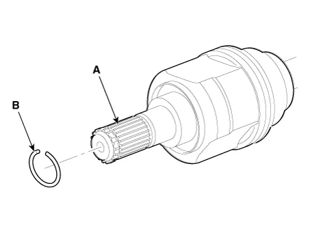
| 2. | Remove the housing circlip (B) from the driveshaft spline (A).
|
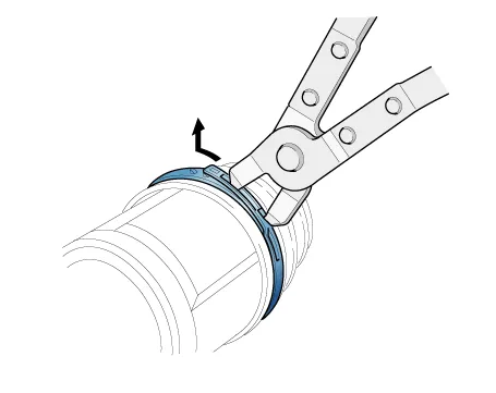
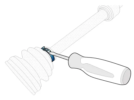
| 3. | Remove both boot bands from the TJ housing.
|
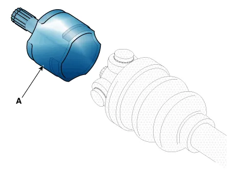
| 4. | Remove the TJ housing (A).
|
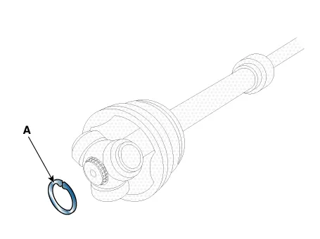
| 5. | Remove the snap ring (A) from the shaft.
|
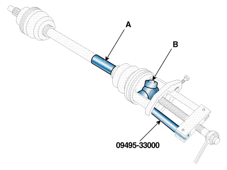
| 6. | Remove the spider assembly (B) from the driveshaft (A) using the special tool SST (09495-33000).
|
| 7. | Clean the spider assembly. |
| 8. | Remove the TJ boot (A).
|
| Inspection |
| 1. | Check the driveshaft boots for damage and deterioration. |
| 2. | Check the driveshaft spline for wear or damage. |
| 3. | Check that there is no water or foreign material in the joint. |
| 4. | Check the spider assembly for roller rotation, wear or corrosion. |
| 5. | Check the groove inside the joint case for wear or corrosion. |
| 6. | Check the dynamic damper for damage or cracks. |
| Reassembly |
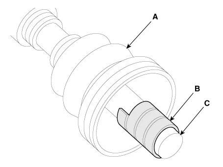
| 1. | Wrap tape around the driveshaft spline(TJ) to prevent damage to the boot. |
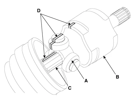
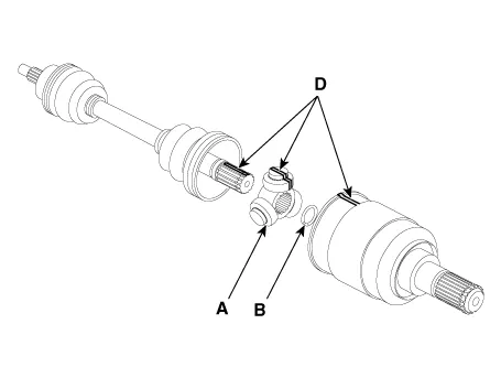
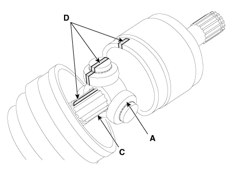
| 2. | Using the alignment marks (D) made during disassembly as a guide, install the spider assembly (A) and snap ring (B) on the driveshaft splines (C).
|
| 3. | Add specified grease to the joint boot as much as it was wiped away at inspection. |
| 4. | Install the both boot band. |
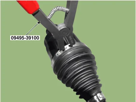
| 5. | Using the SST secure the TJ boot bands. [Hook type]
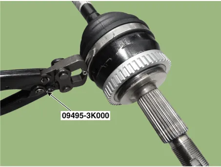
[Ear type]
|
| 6. | Install the front driveshaft. (Refer to Driveshaft Assembly - "Front Driveshaft") |
| 7. | Check the front alignment. (Refer to Suspension System - "Front Alignment") |
Components1. BJ assembly 2. Circlip 3. BJ boot band 4. BJ boot 5. Shaft6. TJ boot band7. TJ boot8. Spider assembly9. Snap ring10. TJ Housing11. Circlip
Components1. BJ assembly 2. Circlip 3. BJ boot band 4. BJ boot 5. Shaft6. TJ boot band7. TJ boot8. Spider assembly9. Snap ring10. TJ Case11. Clip
Other information:
Hyundai Ioniq (AE) 2017-2022 Service & Repair Manual: Heater Core. Repair procedures
Replacement1.Disconnect the negative (-) battery terminal. 2.Remove the heater and blower assembly.(Refer to Heater - "Heater Unit") 3.Loosen the mounting screws and remove the driver's temperature control actuator (A).4.Remove the heater core cover (A) after loosening the mounting screws.
Hyundai Ioniq (AE) 2017-2022 Service & Repair Manual: Rear Corner Radar Unit. Repair procedures
Removal1.Disconnect the negative (-) battery terminal.2.Remove the rear bumper.(Refer to Body - "Rear Bumper")3.Remove the rear corner radar unit (A) after loosening the mounting nuts. • Take care not to separate the bracket from rear bumper when removing the rear corner radar sensor.
Categories
- Manuals Home
- Hyundai Ioniq Owners Manual
- Hyundai Ioniq Service Manual
- Repair procedures
- Hybrid Control System
- Hybrid Vehicle Engine Compartment
- New on site
- Most important about car
