Hyundai Ioniq (AE): AVN System / USB Jack. Description and operation
Hyundai Ioniq (AE) 2017-2022 Service & Repair Manual / Body Electrical System / AVN System / USB Jack. Description and operation
| Description |
The multimedia jack on the console upper cover is for customers who like to listen to external portable music players like the MP3 etc., through the vehicle's sound system when it is linked to this jack. The customer has this added option.
In case of distortions from media connected to the AUX source, the audio unit may not be defective but the output level of the used media does not match the specification of the AUX input.
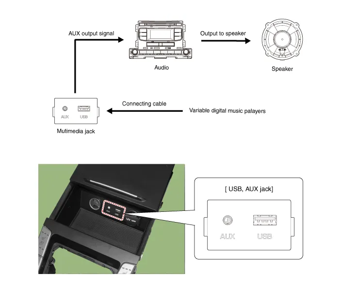
Circuit Diagram
Removal1.Disconnect the battery (-) terminals.2.Remove the floor console assembly.(Refer to Body - "Floor Console Assembly")3.Remove the multimedia jack (A) from the console under cover after releasing the fixed hooks (B).
Other information:
Hyundai Ioniq (AE) 2017-2022 Service & Repair Manual: Climate Control Air Filter. Repair procedures
Replacement1.Disconnect the air damper (A) from the glove box (B).2.Remove the stopper (B) from the glove box (A).3.Remove the filter cover (A) by pressing the knob.4.Replace the air filter (A) with a new one according to the direction of air filter. • To remove the filter easily, press the right side inwa
Hyundai Ioniq (AE) 2017-2022 Service & Repair Manual: Components and components location
C
Categories
- Manuals Home
- Hyundai Ioniq Owners Manual
- Hyundai Ioniq Service Manual
- Engine Clutch System
- Body (Interior and Exterior)
- General Information
- New on site
- Most important about car

Copyright © 2026 www.hioniqae.com - 0.0214